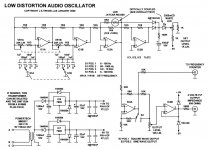
Looks like a Wien bridge to me, just configured a bit differently.
I'd agree with Richiem, Victor's design looks better.
I can never understand how a LDR + PI controller can work properly, seeing as the LDR is a PI control element in itself, or at least a leaky integrator. Everytime I've simulated one it's very difficult to get them to stabilise. By the time I got that AN43 design to work the distortion looked poor.
Does anybody have a spice model for the VTL5C10 ?
I only have Thomas Gootee's VTL5C2 model, the 5C10 is a low slope type.
I've given up on simulating an oscillator in spice. I'm just going to build them from now on. The parts for the LT oscillator should be arriving today. I had bought the VTL5C10 a few months ago so I might as well use them. I can't build something I don't have at least a basic understanding of so Victor's circuit is out for me right now.
Series : C11 || C12 + R20 || R21 + R26 || R27
Parallel : (R28 + R29) || C16
The series part has R/2 and C*2 compared to the parallel in this design
Thanks.
I didn't know you could have a Wein bridge oscillator with unequal arms and have it function. I guess it's just the ratios that matter. There's a whole pile of other stuff in this design that I also don't understand if the actual bridge oscillator is around IC2a. I'm sorry I'm not smart enough to understand this circuit.
At any rate, I think it would be hard to make Victor's circuit a variable one unless the values in the bridge arms were changed.
Is there a way to use some of the ideas in Victor's circuit to modify the LT one?
Last edited:
Is there a way to use some of the ideas in Victor's circuit to modify the LT one?
A variable frequency oscillator is a much more complicated design task than a fixed frequency one. A SVF topology is a much better choice here. Why don't you start your research by looking at variable frequency oscillators? The Tektronix SG505 or the design by Cordell is reasonably easy to understand and DIY.
Samuel
Thanks. I have not been able to find the schematic for the SG505.
Mr. Cordell's article is something I am digesting right now.
SG505 - TekWiki
Right now I'm getting a timeout error from this site, but I'm sure it will be back soon.
Samuel
Right now I'm getting a timeout error from this site, but I'm sure it will be back soon.
Samuel
SG505 - TekWiki
Right now I'm getting a timeout error from this site, but I'm sure it will be back soon.
Samuel
Thanks. It's not working for me either.
I've found a few good sites about really good state variable oscillators. This one stands out:
An Audio T.H.D. Analyser
He provides all the details, including Gerber files, for his project. I don't think I'll use it though. I've found another that seems to be good but is much more simple. Unfortunately I lost the URL, but printed out the schematic. From the above link it seems that the best op amp for these things is a low bandwidth type like the NE5534.
Attachments
If you want to build something simple then that would do. It's not an SVF, it's an all pass phase shift oscillator. I think it was discussed in the first few pages of this thread. Don't expect it to be seriously low distortion or have very good amplitude staibility with frequency.
Your lost link is in post #10 of this thread.
Your lost link is in post #10 of this thread.
Last edited:
If you want to build something simple then that would do. It's not an SVF, it's an all pass phase shift oscillator. I think it was discussed in the first few pages of this thread. Don't expect it to be seriously low distortion or have very good amplitude staibility with frequency.
Your lost link is in post #10 of this thread.
Oh, ok. It looked sort of like a SVF oscillator to me.

back to searching...
Like this one. It's supposed to be super duper, and it's great he's labeled all of the modules, but I still can't follow it very well. I can see it follows the basic SVF oscillator pattern, but it's so complex that I get lost. The rectifier seems excessively complex to me, for example.
Attachments
It's so complex that I get lost.
Well, designing a high-performance variable-frequency oscillator is so difficult that it's just not possible to end up with a trivial schematic. GK's design is still pretty easy--check out the AP System One! Not wanting to offend, but if you have no chance to follow even Victor's simple (yet smart!) design, then designing one yourself is likely just out of reach for the moment being...
What are the specs you need? Can't you meet them with a second-hand oscillator?
Samuel
I was hoping to improve on my Kenwood 204D, and have two unbalanced and two balanced outputs.
Attachments
Thanks. It's not working for me either.
I've found a few good sites about really good state variable oscillators. This one stands out:
An Audio T.H.D. Analyser
He provides all the details, including Gerber files, for his project. I don't think I'll use it though. I've found another that seems to be good but is much more simple. Unfortunately I lost the URL, but printed out the schematic. From the above link it seems that the best op amp for these things is a low bandwidth type like the NE5534.
Hi Dirkwright,
Thanks for bringing this link to my attention; I had been unaware if it. It looks like Glen has done a very nice job of updating my THD analyzer from 1981, using modern parts and using relays to replace those damned rotary switches I had in mine. I have often thought of updating mine by using relays for frequency selection as well. It does take a good number of them, epecially if you cover 11 spot frequencies per decade, but it is worth it, especially in terms of assembly labor. I don't think that Glen provided a link to my article. It can be found at CordellAudio.com - Home under the instrumentation tab.
Cheers,
Bob
I knew I'd seen the all inverter config before:
Low distortion oscillator tests measurement circuits | TMW
I finally got around to looking at this one! It looks very easy to build. Thanks.
The Janascard oscillator is a single frequency inverting Wien bridge circuit much like Victor's. As such it has very limited lock in range with tight AGC and per the author in a message to me will be difficult to convert to wide frequency use.Quote:
Originally Posted by EssB
I knew I'd seen the all inverter config before:
Low distortion oscillator tests measurement circuits | TMW
dirkwright: I finally got around to looking at this one! It looks very easy to build. Thanks.
Cordell's circuit has been implemented by Dick Moore on his site: IG-18 #2, the BIG-18 and works very well as a wide range oscillator as documented by Dick. Dick states he will provide pcb layouts and that board works well.
The board can be incorporated in your box along with PS, switching or relays etc if you like. This is a good way to start rather than all the thrashing around trying to convert single freq circuits to wide band.
Here's an equation which describes the VTL LDR behavior --r2 is very high as the errors of a few percent are offsetting. I plugged the datasheet from the VTL5C9 into Eureqa and went to the deli for a sandwich:
The lines are quite compressed at the low R end, so the errors exceed 10% as the current approaches 40mA.
Edit == Yes, there are too many parens!
An externally hosted image should be here but it was not working when we last tested it.
The lines are quite compressed at the low R end, so the errors exceed 10% as the current approaches 40mA.
Edit == Yes, there are too many parens!
Last edited:
The Janascard oscillator is a single frequency inverting Wien bridge circuit much like Victor's. As such it has very limited lock in range with tight AGC and per the author in a message to me will be difficult to convert to wide frequency use.
Cordell's circuit has been implemented by Dick Moore on his site: IG-18 #2, the BIG-18 and works very well as a wide range oscillator as documented by Dick. Dick states he will provide pcb layouts and that board works well.
The board can be incorporated in your box along with PS, switching or relays etc if you like. This is a good way to start rather than all the thrashing around trying to convert single freq circuits to wide band.
OK, thank you. I'm crest fallen... sigh.
I don't understand why the Janascard oscillator can't be used over a wide frequency range, but that's ok, there are plenty of things I don't understand. Is it because the AGC has limited bandwidth?
I've been to Mr. Moore's pages before and I can't find a schematic for his wide range oscillator. I can layout a PCB board myself.
Last edited:
Thanks David, that looks like a different model - I'll give it a go.
Okay well good. Let me know how it goes.
David.
- Home
- Design & Build
- Equipment & Tools
- Low-distortion Audio-range Oscillator