A quick calculation shows that it should be possible to do with an air coil.
I used this https://coil32.net/online-calculators/multilayer-coil-calculator.html
and approximate dimensions estimated from the pictures.

I used this https://coil32.net/online-calculators/multilayer-coil-calculator.html
and approximate dimensions estimated from the pictures.
May I send you some of the 10K CMF-55 from 2023 and "RN" CMF-55 from 1984?A quick check of some 10K resistors on hand- I had to go up to 30V to get out of the noise floor. The HD3 residual on 2 Dale 1/4W and a Vishay S102 were the same at around -168. I did not want to go to 100V before doing some calculations to make sure I don't fry the resistors. Basically nothing to see here.
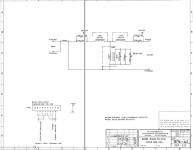
WRT CLT-1 some pictures and the schematic for the low pass filter.
I'll PM my address It should be interesting.May I send you some of the 10K CMF-55 from 2023 and "RN" CMF-55 from 1984?
@1audio Got your PM. I'll send you some samples today. Thanks!
My first series of tests on 15KΩ resistors used the 1984 CMF-55 10K matched to 0.01% in the bottom leg. I saw a little HD2 increase with all DUT so I changed strategy.
The bridge is driven by a ground-referred balanced output and and is recovered by a floating-input balanced "double-twin-T" (quad-T?) notch filter followed by a 5532 INA and cross-coupled THA1246 for CM rejection. The 1 kHz - and generator distortion - appear in common mode. In this situation the notch filter doesn't do much to reject the 1 Khz from the generator as most of the heavy-lifting is done by the CM stage.
When the bridge was all 10K the CM voltage pivoted around 0V. When the bridge was used with 15K in the top arms and 10K in the bottom the CM range shifted which gave rise to small amounts of HD2 in the INA. So I switched to an all 15K bridge and used the MBB0202 and YR1B as the reference resistors.
I couldn't find a combination of MBB/Y1RB that produced distortion. In this test there are 2X MBB and 2X Y1RB with the Vishay pair in diagonal legs.

No matter how I mixed and matched MBB0207 and Y1RB the results were consistent.
When a modern CMF-55 is introduced into the bridge things turn south.

Not good.
I also decided to test the theory that 4X "bad" resistors in the bridge would test great. This is 4X modern CMF-55.

They don't. The FFT looks like a pine forest.
If I were building a resistor tester using this method I think I'd make the bridge amplifier a THAT1510 or INA217 with the bridge connected directly to the bases and program the gain to be about 40 dB. With the THAT1510 input-referred CMRR would be about 90 dB. The INA217, which seems to have trimmed CM resistors it might be about 20 dB better. The bridge would supply bias current from the generator output or extra Rs at the tippy-top and bottom of the bridge pulled down to ground. That way CM rejection isn't affected by added bias Rs.
I'm enjoying this way too much LOL.
My first series of tests on 15KΩ resistors used the 1984 CMF-55 10K matched to 0.01% in the bottom leg. I saw a little HD2 increase with all DUT so I changed strategy.
The bridge is driven by a ground-referred balanced output and and is recovered by a floating-input balanced "double-twin-T" (quad-T?) notch filter followed by a 5532 INA and cross-coupled THA1246 for CM rejection. The 1 kHz - and generator distortion - appear in common mode. In this situation the notch filter doesn't do much to reject the 1 Khz from the generator as most of the heavy-lifting is done by the CM stage.
When the bridge was all 10K the CM voltage pivoted around 0V. When the bridge was used with 15K in the top arms and 10K in the bottom the CM range shifted which gave rise to small amounts of HD2 in the INA. So I switched to an all 15K bridge and used the MBB0202 and YR1B as the reference resistors.
I couldn't find a combination of MBB/Y1RB that produced distortion. In this test there are 2X MBB and 2X Y1RB with the Vishay pair in diagonal legs.
No matter how I mixed and matched MBB0207 and Y1RB the results were consistent.
When a modern CMF-55 is introduced into the bridge things turn south.
Not good.
I also decided to test the theory that 4X "bad" resistors in the bridge would test great. This is 4X modern CMF-55.
They don't. The FFT looks like a pine forest.
If I were building a resistor tester using this method I think I'd make the bridge amplifier a THAT1510 or INA217 with the bridge connected directly to the bases and program the gain to be about 40 dB. With the THAT1510 input-referred CMRR would be about 90 dB. The INA217, which seems to have trimmed CM resistors it might be about 20 dB better. The bridge would supply bias current from the generator output or extra Rs at the tippy-top and bottom of the bridge pulled down to ground. That way CM rejection isn't affected by added bias Rs.
I'm enjoying this way too much LOL.
Very, very informative. Thank you so much for your work!
Hi Demian,
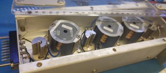
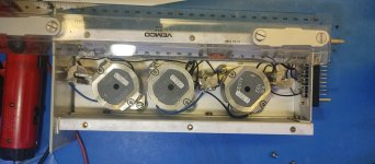
That is a very cool instrument. I loved the USB plug for scale in the first picture. It had to be air core coils, nothing else would work. It also explains the 10KHz test frequency, balancing between HF effects and component size. A really well thought out instrument.
Hi Demian,
That is a very cool instrument. I loved the USB plug for scale in the first picture. It had to be air core coils, nothing else would work. It also explains the 10KHz test frequency, balancing between HF effects and component size. A really well thought out instrument.
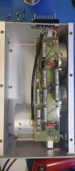
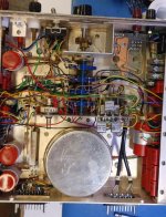
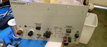
Afew more pics of the CLT-1 innards. The other pics I took years ago. These I just took. The low pass filter may be air core. However the bandpass filter (10 Hz? at 30 KHz) definately uses ferrite cup cores. Schematic attached.
Attachments
My original motivation for replacing the Yageo MFR-25 was to avoid hand-selecting five key values to maintain frequency accuracy and reduce a trim range.
Lowering distortion wasn't the goal.
Imagine however my initial surprise when the 0.1% Dale CMF-55 degraded the oscillator by 15 dB.
Thus began my journey into the rabbit hole of sub ppm resistor distortion.
Now that I've tested the Holsworty Y1RB and the Vishay MBB0207 I decided to see how they performed.
This is the FFT of ULDO post notch filter with a 604Ω load at +20 dBu/100mW.
The 0 dBc level is +20 with +40 dB gain so the HD3 indication at -87 dBu is actually sitting at -147 dBu.
Adding insertion loss of the notch back in, the HD3 level is -141.9 dBc.
HD2, if there is any, is below the noise floor of the 1 Mpt 50 sample avgerage FFT.
The THD for HD3 - HD9 I calculate to be -141.4 dBc or 85 ppb or "five zeros and 85" or 0.0000085%.

For the loaded measurement this is about a 3 dB improvement compared to the Yageo MFR-25 builds.
I'll take the improvement...
Lowering distortion wasn't the goal.
Imagine however my initial surprise when the 0.1% Dale CMF-55 degraded the oscillator by 15 dB.
Thus began my journey into the rabbit hole of sub ppm resistor distortion.
Now that I've tested the Holsworty Y1RB and the Vishay MBB0207 I decided to see how they performed.
This is the FFT of ULDO post notch filter with a 604Ω load at +20 dBu/100mW.
The 0 dBc level is +20 with +40 dB gain so the HD3 indication at -87 dBu is actually sitting at -147 dBu.
Adding insertion loss of the notch back in, the HD3 level is -141.9 dBc.
HD2, if there is any, is below the noise floor of the 1 Mpt 50 sample avgerage FFT.
The THD for HD3 - HD9 I calculate to be -141.4 dBc or 85 ppb or "five zeros and 85" or 0.0000085%.
For the loaded measurement this is about a 3 dB improvement compared to the Yageo MFR-25 builds.
I'll take the improvement...
It makes sense: with a sharp resonant frequency at 30kHz, the 10kHz current will be minuscule and won't generate harmonics. The 30kHz signal may be distorted, but it doesn't matter if some 90kHz is generated since only the amplitude matters for the measurement.Afew more pics of the CLT-1 innards. The other pics I took years ago. These I just took. The low pass filter may be air core. However the bandpass filter (10 Hz? at 30 KHz) definately uses ferrite cup cores. Schematic attached.
If the 30 kHz HD3 from the component is of sufficient amplitude to distort the magnetics in the 30 kHz BP filter its probably measuring a really bad part. Like maybe one of my CMF-55s.It makes sense: with a sharp resonant frequency at 30kHz, the 10kHz current will be minuscule and won't generate harmonics. The 30kHz signal may be distorted, but it doesn't matter if some 90kHz is generated since only the amplitude matters for the measurement.
") 1audio should have the samples in a few days.
1audio should have the samples in a few days.It would probably be possible to reuse the very sound and sensible principles used in this instrument in a much simpler DIY tester. It wouldn't be a clone or a copy, but rather a tribute, having significantly reduced performances: for example, a measurement floor 40dB higher than -170dB. -130dB would still be incredibly useful for most DYIers.
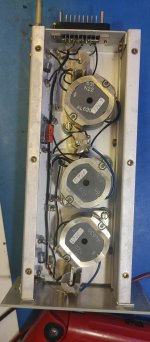
One question mark remains: the transformers. I don't see which trick to use to achieve a -130dB HD3 level with magnetic materials, even if the magnetising inductance is huge, and the peak induction minimal
One question mark remains: the transformers. I don't see which trick to use to achieve a -130dB HD3 level with magnetic materials, even if the magnetising inductance is huge, and the peak induction minimal
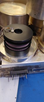
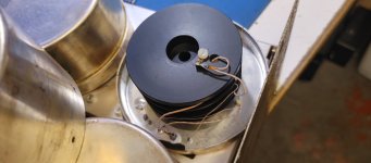
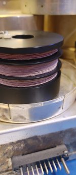
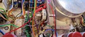
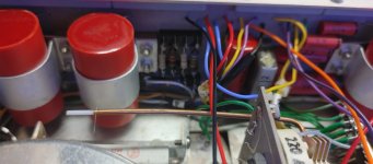
Here are some pics of the transformer module. The coil may be on a plastic former. The wire is litz. There is also the short piece of semirigiid used as some type of gimmick capacitor you can see in two pictures. The Vishay S102 10K reads -170 dB 3HD at 30V. i'll try some other resistors later. This instrument was invented by Siemens to select high reliability parts in the late 1950's. They wanted to be sure the undersea repeaters would not fail. Radiometer constructed the commercial version in the 1960's. There is a newer version with relays and a lot more automation. These were never big sellers. Dynavector used one to select parts for their preamp. Vishay film resistor group also has one. They are mostly in Japan I believe.
PM me if you want a copy of the manual.
PM me if you want a copy of the manual.
Attachments
-
 20240426_113818_HDR.jpg188.8 KB · Views: 11
 -
 20240426_113931_HDR.jpg179.2 KB · Views: 10
 -
 20240426_113935_HDR.jpg227.1 KB · Views: 11
 -
 20240426_114433_HDR.jpg304 KB · Views: 10
 -
 20240426_114522_HDR.jpg273.6 KB · Views: 10
 -
 20240426_114606_HDR.jpg193.8 KB · Views: 10
 -
 20240426_113808.jpg379.4 KB · Views: 11
- Home
- Design & Build
- Equipment & Tools
- Low-distortion Audio-range Oscillator