Thank you Jack,
hopefully there's going to be enough interest to spark some ideas. The IG18 and brethen are really nice and the discrete switched networks make them really interesting... a modernization of the circuit can make this generator a really nice lab tool
Is anyone interested in updating/designing the PCB?
I can certainly do it -- but which design.
OK so I have been looking around at all viable projects, starting from the venerable regreening of the IG18 article of the 70s.
I think that the design with the highest potential is the Super IG18SL design, by Steve Lafferty Modifications: Heathkit IG-18 Audio Generator
and
http://www.tronola.com/IG-18SL_Construction_Notes.pdf
Larry Burk designed a PCB in Eagle and the files are downloadable form Tronola website.
The basic design is there, however Dick Moore experimented with the design - and I believe much improving it - with more current and still available parts (especially opamps).
There are three separate parts of this project which i believe the interested parties here could address:
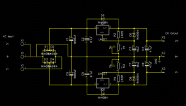
1- updating the power supply to something actually modern. The PS is somewhat present in Lafferty's board and I think it should be redesigned as it involves powering the device with a tranformer wired for 240V but connected to 110, which is very unpractical for us living this side of the ocean. So something based on the ubiquitous LM317 and LM337 pair would be optimal I think (Dick mentions this in his writeup).
2 - redesigning the PCB to account for double layer and actual components used for the more modern opamps that need less ancillary discrete components (something that Dick Moore pointed out in his writeups here:IG-18 #3, the IG-339A
and here:
IG-18 #4, the IG-339B
possibly avoiding any Tantalums and resizing the layout so the parts actually fit on the board...
and finally, 3 - debating and finally choose the best and easiest solution for the multiplier network.
Use the existing tuning network of the 18/5218, as Dick Moore did admittedly simplifying things and also making it cheaper, just adding the AGC caps. Point here is to avoid the uber expensive switch from Mouser, and possibly the purchase of 8 expensive precision caps, discarding the ones already inside the IG18.
All switches for the frequency use 1/2 W and 1% resistors, would using 0.1% improve things? Dick Moore also suggests changing the attenuator network to reflect HP 339, but I am not knowlegeable enough to evaluate cost/benefits.
Hopefully we could also come up with a BOM that we can use with the whole project.
In the end, I would like to acknowledge the work of Steve Lafferty and the late Dick Moore R.I.P., and also I will ask Mr, Lafferty if he would be interested in hosting eventually any update we could come up here on his site, as a follow up on his excellent work.
IG18-SL -- based upon the HP339A.
Might want to use a compound amplifier instead of 1/2 of a 2134 on the output.
Exactly! That was what I was referring to.
Ok, although I'm scared what prices could uF size caps could cost in MLCC.
Wima MKP are radial, available in 50/63 and 100V. Would need to parallel the multiples of (4.7uF || 270n), (470n || 27n) etc. to get within 1%
Well, I was looking at the schematic from Lafferty's page and attempting to figure out how Dick modded the design, and also how the Eagle PCB that is suggested fit in all of this. And I had a crazy idea...
basically, to make the whole design in SMD, and moving the AGC and multiplier networks on the PCB itself, using the original Heathkit switch just to select the combinations to reach the optimal cap values (i.e. paralleling them on the PCB and using whenever possible, precision SMD parts). It would simplify a lot the build and avoid going crazy with difficult to find rotary switches and routing lumps of paralleled caps.
Still, something that i dont think I can do although I am trying to understand how DipTrace works (and it will NOT import the Eagle file that's on Tronola's page). Would anybody be interested?
If you want to make it a popular SMD project, use 1206 passive devices where possible. Not only are they easier to solder by hand, they seem to be more thermally stable.
I bought a kit of 1206 resistors from Jameco and they are accurate to better than 1%
Mouser shows a lot of C0G/NP0 MLCC in 1206.
I bought a kit of 1206 resistors from Jameco and they are accurate to better than 1%
Mouser shows a lot of C0G/NP0 MLCC in 1206.
Ok , so I tried to draft a PCB using the base Eagle board that Tronola hosts on the website. I tried to replace the old PS section with a more modern one pilfered somewhere on the net (I used only the schematic and edited in DipTrace), that uses the LM317T and LM337T (both high voltage versions so they accept the rather high voltage coming from the trafo). I also rerouted all top traces so that they should work as an actual layer and not as a simple guide to add top patch wires.
As it is quite late , I will just post gerber and diptrace file... i am NOT able to redraft the board using 1206 SMD, I'd love it if some good soul would like to do so. As it is now, I'm posting this not as a working board rather to have more knowledgeable people than me take a look and possibly help me debug it and improve it so that a final version can be made and have it available for the Heathkit 18 / 5218 audio generator fans.
Tell me if I made horrible mistakes, and how to correct them!!
Franco
Attachments
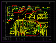
And here's the latest revision. Hopefully I managed to edge out the worsy problems. I also dowloaded the free version of Eagle (jeeeez it's really HARD to learn that.).
So I've exported it in Eagle .brd, maybe more perople can take a look at it this way.
So I've exported it in Eagle .brd, maybe more perople can take a look at it this way.
Attachments
Last edited:
It appears to me that one of the major pains in modifying the IG-18 to use HP339 oscillator architecture is the need for additional wafer switch sections in the decade range switch. This is especially the case in the Moore version having capacitor ratio of 10 (rather than 100 in HP design)--- the existing decade range switch would suffice with two more poles to accommodate the added AGC range switching.
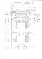
Please see switch sections S1B and S1E, Schematic Page 1 of Steve Lafferty Modifications: Modifications: Heathkit IG-18 Audio Generator I suggest these two functions can be accommodated by a dual 1 of 4 analog mux, https://www.vishay.com/docs/70062/dg408.pdf The sketch below details how the address selection of the mux can be derived from the existing decade range switch. All that follows deserves critical scrutiny, as it is pure paper musing.
The sketch depicts the active stage of the oscillator as a mental aid. Two points (E0 and E1) within the range switch are selected for position sensing: I believe both points switch to either Ground, to Oscillator Output (having average of 0V), or open circuit. Each of the sense lines is conditioned with a light pull-up to +15V and a low-pass filter to suppress the sine waves at the oscillator output. Thus, each mux address pin is presented with either 0 or +15V; I believe the range switch exercises the address bits through all 4 binary states and I believe sensitive capacitor nodes are well isolated from the mux by the pull-up/LPF networks.
This idea probably has little value if the HP design with 100 cap ratio is preferred.
Thoughts?
Attachments
Hello BSST,
it actually makes a lot of sense, and i have indeed been reading with attention Lafferty's website in regards to the IG18. Sticking to the 10x ratio does make things simple, and Dick also noted that using an order of magnitude more for the ratio could give debatable practical advantages anyway...
Implementing it may not be exactly easy, though.
I have to study, I am not so competent - but that is the direction I want to ultimately go. Ideally I wanted to take steps, maybe implement this idea using the original IG18 rotary switch and using solid state switching for the AGC range; then, the final goal is to convert the board to full SMD (moving the PS to a separate board placed where the original sits).
For now thank you for your help and suggestions!
Franco
Question, after reading the 339 manual.
How precise must the range caps be? The ones in the IG18 have 2% on them, althoug the tolerance is in spec for each cap, the differences between the various caps are not; i.e. the 5uF cap measures 05.128 uf on my LCR meter, while the 0.5uf measures 0.5056... and the next one actually is 0.0495
I image that I should try to obtain the closest value for each cap to preserve accuracy? I.e. 5.128/.5128/.0513/.0051/.0005 right?
Alternatives are buy better, lower tolerance caps...
The ones in the IG18 are film caps, but I cant find better tolerance caps on Mouser or digikey.
Or build caps bundling them together.
Opinions?
I apologize for the obvious noob question
- Home
- Design & Build
- Equipment & Tools
- Heath IG-18 IG-5218