Hello everybody,
Since I have noticed a very positive effect on the sound of several end devices through Ethernet isolators directly in front of the end devices when streaming music, I am currently working on their construction and building some myself.
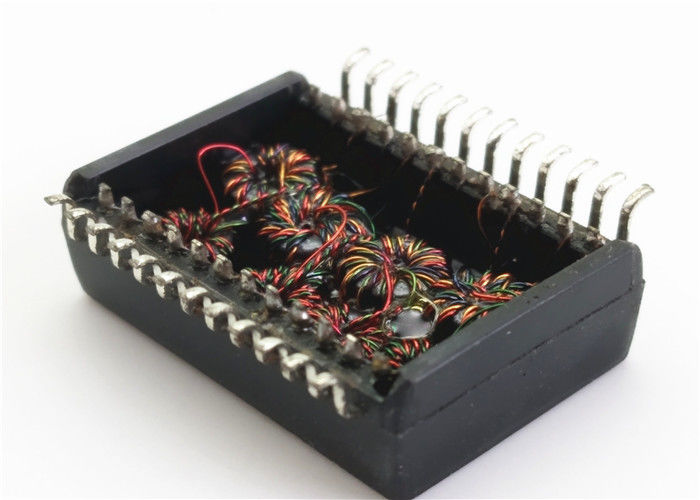
Ethernet magnetics are used for isolation, which are also used for coupling with Ethernet end devices. These usually consist of a transformer with a common mode choke behind it. This reduces noise on the line, which is noticeable in the better sound.
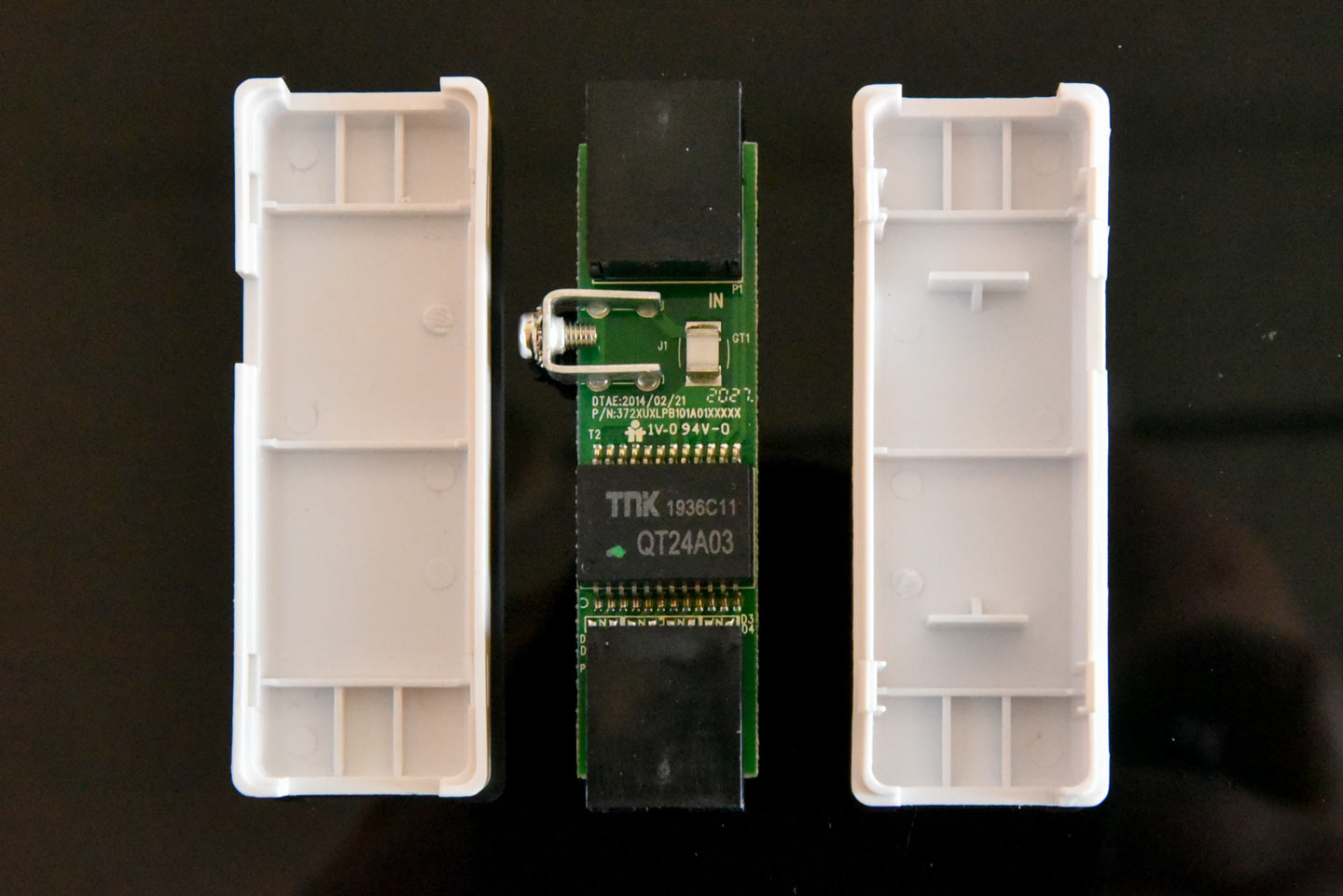
Picture of the DeLock Isolator:
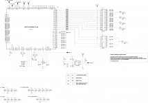
Here is picture and a circuit diagram of a typical 100BaseT transformer:

The center taps on the cable side are terminated with the Bob Smith termination: termination with 75Ohm resistor and 1000pF capacitor to ground.
The center taps on the PHY side of the transformer are integrated in the connection to the PHY.
As you can read here, the Bob Smith circuit is not without controversy: Why is Bob Smith termination for Ethernet recommended if it's wrong? - Electrical Engineering Stack Exchange
When using the Ethernet magnetics as an isolator, it is in the middle of the cable - so it has no PHY side.
Are there any suggestions as to whether the center taps should also be terminated with bob smith termination or whether not to terminat? Should one make the termination against earth?
Would really be grateful for any input.
Best regards,
Tom.
Since I have noticed a very positive effect on the sound of several end devices through Ethernet isolators directly in front of the end devices when streaming music, I am currently working on their construction and building some myself.
Ethernet magnetics are used for isolation, which are also used for coupling with Ethernet end devices. These usually consist of a transformer with a common mode choke behind it. This reduces noise on the line, which is noticeable in the better sound.
Picture of the DeLock Isolator:
Here is picture and a circuit diagram of a typical 100BaseT transformer:
The center taps on the cable side are terminated with the Bob Smith termination: termination with 75Ohm resistor and 1000pF capacitor to ground.
The center taps on the PHY side of the transformer are integrated in the connection to the PHY.
As you can read here, the Bob Smith circuit is not without controversy: Why is Bob Smith termination for Ethernet recommended if it's wrong? - Electrical Engineering Stack Exchange
When using the Ethernet magnetics as an isolator, it is in the middle of the cable - so it has no PHY side.
Are there any suggestions as to whether the center taps should also be terminated with bob smith termination or whether not to terminat? Should one make the termination against earth?
Would really be grateful for any input.
Best regards,
Tom.
Last edited:
Example of a 100MB/s ETH switch I designed from MICREL application note. Works perfectly.
An ETH transformer shall be plugged to the PHY transceiver on one side and RJ45 connector on other side. It exists RJ45 connectors with magnetics inside the body so a direct connexion to the PHY transceiver is allowed.
An ETH transformer shall be plugged to the PHY transceiver on one side and RJ45 connector on other side. It exists RJ45 connectors with magnetics inside the body so a direct connexion to the PHY transceiver is allowed.
Attachments
PHY on one side and RJ45 on the other is the normal use case.
But if a transformer is placed in the middle of the cable to filter noise, as is the case with the isolators, then there are RJ45 on both sides.
The question for me is whether the center taps should be terminated with 75 ohms and a condenser on both sides?
But if a transformer is placed in the middle of the cable to filter noise, as is the case with the isolators, then there are RJ45 on both sides.
The question for me is whether the center taps should be terminated with 75 ohms and a condenser on both sides?
For some kinds of conducted RFI/EMI noise it may be necessary to do some experimentation and measurements to find out what works best in the particular circumstances where there is a problem.
The purpose of the 75-ohm resistors and cap connecting transformer center taps to ground kind of looks to me like a way to help dissipate high frequency components of transformer phase imbalances and or common mode coupling through the transformer. The resistors are probably chosen to dampen unwanted transformer output signal imperfections and dissipate their energy as heat in the resistors.
The component values and circuitry are likely particular to the design shown in the schematic.
If you are asking about adding similar circuitry on the primary side of the transformer then the effects of that would have to be evaluated. It might help or it might hurt performance. Modeling and measurements would be advised to help understand the consequences.
However since this is for audio, one could always let one's ears be the guide. Is the sound the same, better, or worse with a change to the circuit design?
My observation of numerous devices with 100MHz Ethernet connected through an RJ45 jack is that ***all*** of them contain an internal magnetic coupling transformer positioned between the PHY transceiver IC chip and the RJ45 jack.
Some manufacturers of RJ45 jacks offer models where the magnetic coupling transformer is embedded inside the housing of the RJ45 jack itself.
This leads me to ask this question:
What is the value of adding an ***additional*** external magnetic coupling transformer?
When ***total*** electrical isolation is desired it might be better to use “Ethernet-to-fiber” media converter devices. Look up “media converter” on ebay or alibaba to see examples of low-cost commercial devices which do this. These devices typically have one RJ45 jack and one SFP slot. The SFP slot holds a fiber transceiver module appropriate for the desired type of fiber cable (single-mode, multi-mode, etc.) Two such media converter devices may be connected back-to-back with a fiber cable in between them. This provides a totally isolated data path between the two RJ45 jacks.
-EB
In order to let one's ears be the guide, it has to be a double blind comparison (with levels matched). Otherwise it's letting one's ears and sight be the guide.However since this is for audio, one could always let one's ears be the guide. Is the sound the same, better, or worse with a change to the circuit design?
My observation of numerous devices with 100MHz Ethernet connected through an RJ45 jack is that ***all*** of them contain an internal magnetic coupling transformer positioned between the PHY transceiver IC chip and the RJ45 jack.
Some manufacturers of RJ45 jacks offer models where the magnetic coupling transformer is embedded inside the housing of the RJ45 jack itself.
This leads me to ask this question:
What is the value of adding an ***additional*** external magnetic coupling transformer?
When ***total*** electrical isolation is desired it might be better to use “Ethernet-to-fiber” media converter devices. Look up “media converter” on ebay or alibaba to see examples of low-cost commercial devices which do this. These devices typically have one RJ45 jack and one SFP slot. The SFP slot holds a fiber transceiver module appropriate for the desired type of fiber cable (single-mode, multi-mode, etc.) Two such media converter devices may be connected back-to-back with a fiber cable in between them. This provides a totally isolated data path between the two RJ45 jacks.
-EB
+1 exactly this. Also counts for the meanwhile standard Gbit switches and was already like that with 10 mbit switches....
Anything deviating from already perfectly fine working standardized devices and techniques should be observed carefully.
Last edited:
I was also skeptical when I read reports that an isolator would improve the sound, but had to find out that this was true.
The transformer chip not only has a transformer but also an integrated common-mode coil that filters noise. In my opinion, this may have the greatest influence on the sound improvement. It's not about isolation, it's about reducing noise.
The transformer chip not only has a transformer but also an integrated common-mode coil that filters noise. In my opinion, this may have the greatest influence on the sound improvement. It's not about isolation, it's about reducing noise.
This is a good point and is especially relevant when adding an external device such as an isolator, filter, or even a specialized “audiophile” cable.In order to let one's ears be the guide, it has to be a double blind comparison (with levels matched). Otherwise it's letting one's ears and sight be the guide.
Keep in mind that digital signals are relatively immune from being degraded by noise or other interfering signals.
The place where reducing noise in the desired signal is most important is in the analog section.
During the 1980’s and 1990’s several CD player manufacturers experimented with internal optical isolation between the CD transport and the DAC/analog output section. However this eventually fell out of favor. My experience was it sometimes caused issues that didn’t occur in non-optically-isolated CD players.
Later high-end disc players (Sony DVP-NS999ES for example) have direct electrical connections between the transport section and the analog section. However the DVP-NS999ES does have ***entirely*** separate power supplies for its digital vs. analog sections. The analog power supply section of the DVP-NS999ES is entirely “linear” and has a 60Hz power transformer. No “switching regulators” are employed in the analog section.
-EB
Its not that I think the signal and bits are getting worse by noise.
But the noise effect the process of converting digital data into analog signals.
The aim must be to keep the dac free from noise.
And yes, I trust my ears, which clearly hear a strong improvement from the isolator / transformer.
If you don't believe this, you should try it yourself.
But the noise effect the process of converting digital data into analog signals.
The aim must be to keep the dac free from noise.
And yes, I trust my ears, which clearly hear a strong improvement from the isolator / transformer.
If you don't believe this, you should try it yourself.
Then please let us know how to set up the comparison so that our sight isn't involved in evaluation.If you don't believe this, you should try it yourself.
This is some BS. Every single BASE-T Ethernet interface already has a transformer on both sides on the MDI side of the PHY.
The purpose of the 75-ohm resistors and cap connecting transformer center taps to ground kind of looks to me like a way to help dissipate high frequency components of transformer phase imbalances and or common mode coupling through the transformer. The resistors are probably chosen to dampen unwanted transformer output signal imperfections and dissipate their energy as heat in the resistors.
Sounds like a made-up explanation full of buzzwords. Output signal imperfections?
However since this is for audio, one could always let one's ears be the guide. Is the sound the same, better, or worse with a change to the circuit design?
Or, since it's Ethernet, you can just use the proper equipment and look at the eye diagram instead of lying to yourself.
Its not that I think the signal and bits are getting worse by noise.
But the noise effect the process of converting digital data into analog signals.
The aim must be to keep the dac free from noise.
And yes, I trust my ears, which clearly hear a strong improvement from the isolator / transformer.
If you don't believe this, you should try it yourself.
There's already a transformer with CMC at each end. You are imagining things.
This is some BS. Every single BASE-T Ethernet interface already has a transformer on both sides on the MDI side of the PHY.
Trying to explain the technical aspect to other members on these forums should not involve those words, that's just so bad...
Maybe the additional transformers change cable impedance/noise spectrum, and that sounds better to them, in their systems, for whatever reason...?
Instead of telling them that what they do/hear is BS, pointing them to the relevant reading material / white papers would be more beneficial.
Since I have noticed a very positive effect on the sound of several end devices through Ethernet isolators directly in front of the end devices when streaming music, I am currently working on their construction and building some myself.
It's weird since there is already an isolation transformer on both sides.
Unless... Is your patch cable the shielded type? These are the ones with a metal shield around the male RJ45 connector. That connects the cable shield to chassis ground at both ends, defeating the isolation.
Is the device 100M ethernet or 1G? Does it switch from 1G to 100M with the isolator on?
yes, the whole thing is really strange and I'm trying to explain it to myself up to date. Before my experience, I was also upset in various forums about the "nonsense" of audiophile switches. Until I tried the isolator and saw that something sound relevant was happening on the Ethernet route. Feel free to google it, there are many reports about it. The DeLock isolator costs only 20 € (a bargain), everyone should order from Amazon and send it back if they don't like it. to the questions: I use unshielded cable and only the two pairs necessary for 100baseT and that on both sides.
You can get 100Mbps working fine over chicken wire probably. I strongly suggest you perform a blind listening test before you dump any more time and money into something that is hard to imagine. Adding two more transformers when you already have two and you have UTP cable is not going to help.
Hi I have worked for a very long time in a business where ethernet was the most common cabling besides optical fibers. We measured cabling and connections in polluted industrial environments. As I am audio hobby guy since I was a child of course I gained experience for the hobby as well. We measured cabling with very expensive equipment and saw differences between brands, types of cables (UTP, FTP, STP, SFTP...) and even iron cables that were introduced (but very soon these were excluded). Stranded, solid, CAT 5, CAT 5E, CAT 6, CAT 7 etc. etc. All connections were extensively measured and the report was delivered and stored. Of course we sometimes went to the maximum allowed distance, used cables in places where one should don't lay cabling and got what was to expected.
Despite the quite weak plugs ethernet has evolved and can be very reliable when things are done right according how stuff is defined. If someone starts messing by inserting superfluous parts and doing things by ear I am very curious how this will measure and how it will interact in standard ethernet environments. It all seems the same thing again: people with often quite visible shortcomings in their audio setup will go in great lengths to start solving things that are not a problem.
That having said ... I have listened to such guys that now have even audiophile UTP cables... Audio ethernet switches etc. There is a new niche market where people can dump their excess money. As usual looks and sexy brand names are the largest differences besides the extreme prices. I have yet to meet a PCB in such equipment that was not bought from a known network company 😉 The differences I experienced were marginal and certainly not worth the money so I took that as a given. The people that sell them are very enthusiastic though 😀 As I build linear PSU's for a hobby I tried these out on ethernet switches. To my astonishment I could easily hear the difference... I should not say this and I paid no further attention but I kept the linear PSU's 🙂
Last edited:
- Home
- Source & Line
- Digital Source
- Layout of Ethernet Isolators