Hello everybody,
it's quite a while that I had a look at this thread, quite some development - and all based on ManoloMos' work! Nice to see!
ManoloMos, also from my end a big thanks for all the help you provided by sharing your work!
You may remember, I have commented on a different thread that I am busy as well with replacing the LD (in a SOAD70A) - and I actually managed
to get the pickup running a few days back.
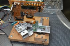
I have used what I had, no complex amplifiers or alignment tools. My 'rig' has been changed a few times, and I got by chance a linear bearing with rail which is used for one axis and the other axis are 'homemade'. The SOAD70A does not have a grating which makes it a bit easier. The original servo PCB is used to drive the lens and to supply the LD. Unfortunately, I did not find one with the correct polarity for the photo diode, therefore the signals needed to be inverted.
Signal for A-D are connected to very simple I/V amplifier (TL074).
I do not use a mirror, I am using a piece of a CD which is aligned using a working pickup. With a mirror the signals were not symetrically, I therefore
took the CD (that is where the laser should look at anyway 🙂 .
When the pickup was replaced after alignment, it acutally read the TOC and played right away. Only some minor adjustments were required.
Please find a few impressions of my work. To be continued.
Greetings from NL!
it's quite a while that I had a look at this thread, quite some development - and all based on ManoloMos' work! Nice to see!
ManoloMos, also from my end a big thanks for all the help you provided by sharing your work!
You may remember, I have commented on a different thread that I am busy as well with replacing the LD (in a SOAD70A) - and I actually managed
to get the pickup running a few days back.
I have used what I had, no complex amplifiers or alignment tools. My 'rig' has been changed a few times, and I got by chance a linear bearing with rail which is used for one axis and the other axis are 'homemade'. The SOAD70A does not have a grating which makes it a bit easier. The original servo PCB is used to drive the lens and to supply the LD. Unfortunately, I did not find one with the correct polarity for the photo diode, therefore the signals needed to be inverted.
Signal for A-D are connected to very simple I/V amplifier (TL074).
I do not use a mirror, I am using a piece of a CD which is aligned using a working pickup. With a mirror the signals were not symetrically, I therefore
took the CD (that is where the laser should look at anyway 🙂 .
When the pickup was replaced after alignment, it acutally read the TOC and played right away. Only some minor adjustments were required.
Please find a few impressions of my work. To be continued.
Greetings from NL!
Attachments
I would also prefer properly repaired and adjusted laser pickups before china clones.Hi Guys as an owner of 2 Sony CDP227esd, I am watching this with great interest. I really think you guys are really talented and should go into business selling restored laser Lenses. There is I believe still a Huge market for people whom love their CD players but are disappointed by the cheap imitations from China.
I would be happy to pay good money to have a spare laser for my Players, But I am not willing to take the risk of the China ones.
Again Bravo to all 3 of you.
regards from Australia.
Unfortunately for my case, with my KSS-168A Lasers, by now I damaged 7 of them and could not fix one properly.
If I ever should succeed I will certainly try to help out others by repairing their laser pick ups.
For now I would say that I had 50% success since I managed to get one working with a new Laser diode.
Still I think that in my case, the main cause for a none working Laser pickups is not the Laser itself but more likely the photodiode.
I imagine, that the plastic in which the photodiode is poured in, becomes impermeable to the light of the laser diode.
Thanks for this information! I Think I will try to use a CXA1081 as well since this is the same chip that is used in my CD Player.Hi Ruzki,
The schematic I used is the one that Manolomos published and it is the same you used also.
What I added is a SONY CXA1081, it is the IC that can be seen on the board. I'm using only the APC power supply function for the laser diode.
For the power supply I'm using a dual lab power supply but I added on the PCB a LM7815 and a LM7915 with usual filtring.
There is no other filtring on the inputs.
I tried lasers which were installed in KSS-210B pickups. This Lasers worked on my bench but not in my CD Player.
There must be a difference in the laser pickups which causes the pickup not to function when installed in the Player.. I guess.
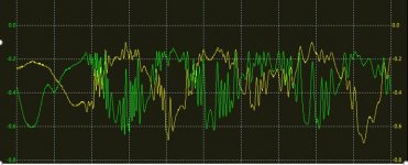
Also I noticed that signals of the E and F Diodes switched polarities when KSS-210B Laser diode was used -> picture attached.
before and with old Laser diode:

after and with new KSS-210B Laser diode:

Congratulations to ASAMS fom Nederland!
About member Ruzki issues. Well, KSS-168a. I've never have seen it in my hands, but it looks in the pictures, that is a bit more difficult to place in the "gig" for to manipulate and adjust. Another problem are the screws in the lens base, tht in your case, it seems impossible to manipulate or adjust with a CD running. This is a problem. In KSS-151, 272, etc... this screws can be adjusted, it is not easy, but it not impossible, but KSS-168a is another history... more difficult.
Another thing, in the pics, I've seen all the signals you have published, and all are bad signals, all looks like out of focus.
If I were you I'd practice with a kss-213a or similar for to see how a well adjusted laser pickup works, and how it plays the signals.
This is a KSS-151a not repaired A-B-C-D signals
About to use a CD like a mirror, is not problem, but a real mirror reflects more light, and you can adjust the laser at minimun and get a lot of signal. I've used some mirrors, and some of then does not work well, I don't know why.
Best regards
Gracia,s ManoloMos!
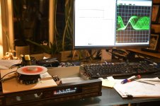
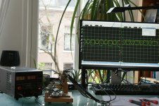
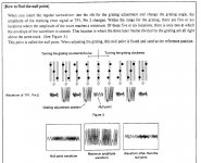
There is another aspect using the CD, if you move the lens in 'tracking' direction (from one track to the other) and not just in 'focus' direction, (up and down)
you can actually see the pits (when laser spot is in focus).
One missing step I suffered from was that the signals for A-D indicated 'in focus - but actually the position of the cylindrical lens defines the layer where
exactly 'in focus' is, and that may not correspond with the pits (or the surface of the mirror).
Hence, one critical point is to adjust the cylindrical lens so that when signal A-D confirms 'in foucs' (just a spot on the diode array) the 'RF' sgnal has a maximum. Here's a snap shot how the signals would look like when the 'tracking' direction is actuated (to 'scan' the surface).
Kind regards!
Attachments
So good reading your posts! Success!
I am very much consumed with other work
but hope to chime back late in autumn 2022.
For the meantime:
What about using modern laser diodes?
All diodes from the dawn of the CD-era are not available or simply fakes.
I tried 1rst gen Sharp LT022MC diodes (about 40) from differnt dealers,
they were all crap.
QSI offers diodes with different connections (common anode/cathode for laser/monitor diode etc)
They should be very versatile.
http://qsilaser.com/download/Infra_Red/QL78F8SX_2019.pdf
I can provide mechanical adaptors from 5.6mm to 9mm.
But pins have to be adapted and APC redesigned as modern diodes need less power.
Hello Salar,
I have tried with Rohm (RLD78MZA6) and Arima (ADL78501) LDs, both purchased through suppliers for electronics (e.g., the Arima can be bought from Conrad or Reichelt, the Rohm from RS or Franell). They need about 30mA , and they both give about the same signals (the Arima is a bit more powerful).
They both showed signal intensities similar or higher than a working pickup (in my test and alignment equipment)
However, they both do have different polarities than I would need for my project (the Technics SOAD70A) and need adjustments in the electronics.
The QSI laser diodes would be a nice option but I would understand that one needs to order a whole batch (500 - 1000 pcs), there is no vendor for them..
I even would also believe that with the current problems and shortages, it would take months to get them.
Anyway, 'to be continued' 🙂
QSI has a sales agents in Europe:
- serge.broers@te.com
- he is for Benelux, maybe you can get free samples from him?
- If this contact does not help, I can drop by personally at the Eropean office first half of January!
- Best, Salar
XMas - time (best wishes to all), first time to read the entire thread, two basic questions:
The reflective mirror:
1: Shouldn’t it be 1.2mm polycarbonate
because of the refraction-index?
2:What happens if the grating window gets misaligned/shifted? This can happen easily with the BU-1C as it is under pressure from a spring and only secured by threadlock - paint.
When I get it correctly, shifting the grating results in the side beams being
weaker, but their angle is not shifted-correct?
Again, how crucial is a misaligned diffraction grating?
Ist there a sweet spot at all?
Will a misalignment result in weaker sidebeams hitting the E-F
photodiodes or will it also result in shifted angles of the sidebeams?
See also the basics of diffraction:
https://physicsopenlab.org/2017/08/29/laser-diffraction-grating/See also this
Best, Salar
Ist there a sweet spot at all?
Will a misalignment result in weaker sidebeams hitting the E-F
photodiodes or will it also result in shifted angles of the sidebeams?
See also the basics of diffraction:
https://physicsopenlab.org/2017/08/29/laser-diffraction-grating/See also this
Best, Salar
Last edited:
Hello Salar,
hope life treats you well.
I would believe it's quite crucial and it also seems to be difficult to adjust. The entire focusing and reading process is a balancing act 'Drahtseilakt' for
the laser beam and the mechanism, one little 'tick' and it would fall down. On the other way, these pickups needed to be adjusted once, so it must be possible - it 'just' requires a good 'feelng', a bit of experience and some alignment tools.
Best,
Andreas
p.s.
I found this in a Pioneer service manual (PD-4700/5700/6700).
Attachments
Dear Andreas,
hope life treats you well as well!
Thanks a lot for the Pioneer SM.
I think, Yamaha had the same alignment as well.
Ok, so only the angular position seems to be crucial,
but not the horizontal position.
I was asking because in a Sony KSS-123A or BU-1(C)
the diffraction grating has a lot of horizontal play, about 1mm.
It is secured by threadlock (Schraubensicherungslack)
It is also pressed down by the diode with a spring.
Two washers spread the force of the spring evenly
over the plastic frame of the grating.
But but when only a tiny amount of threadlock is used,
chances are very high that the grating peels off
when the diode is removed.
This happened in one BU-1 while disassembling.
As far as I remember, there is no access to the grating
once the diode is installed and ready for machanical alignment.
Dear Salar,
sorry, again quite late with my response. Unfortunately, I can't answer your question since I didn't need to do any grating alignment so far.
I would believe that the adjustment is one of the last things done during alignment. Means, in a first step the 4 diodes would need to be centered, and once
this is done the grating, and maybe repeat step one. That would mean there should (must) be a way to access the grating.
Unless (just a guess) there was a special optical 'bench' that was used to perform this adjustment before .
Hope some other members have some (better) ideas ..
Hi all! I'm trying to build alignement board based on @Manolo Mos schematics and @ruzki PDF, because i have a Pioneer PDR05 (PEA1326) that needs laser alignement due to diode swapped from another PDR05 unit. I have some questions, hope someone could help me:
Emanuele
- I don't have OPA AD826 for photodiodes, may i use LM358 as used for coil Exciter?
- @ruzki in your schematics i don't understand what are pins VREF_EF, VREF_BD, VREF_AD, VREF_BD
- What is the purpose of R1, R2 and R3 in the focus coil exciter schema?
Emanuele
Last edited:
Hello Emanuele!
My results using oder op-amps other than AD826 have not been good. Just read through my previous posts.
The VREF´s are there to set a base voltage for the oscilloscope. With these you can adjust the baseline to 0V.
I'm not sure about R1, R2 and R3, I have a newer schematic that I have attached to this post.
Attachments
Hello. Yes, you can try LM358 or any other op amp, or any other design that amplify the diode array signal. This signal is tiny, is low frequency but is tiny, and can be noisy. I'd recommend to make the circuit in a holed circuit for projects, and use sockets for the op amps. In the next days I hope to work in a KSS-272a that sent me a forum member, and a KSS-151a that I bought on Ebay.
About the PEA1326, I don't know nothing about this laser pickup, looking in google, it seems like pwy1010 and similars. I haven't tried to replace laser diode in Pioneer, but it does not seem easy. The original laser diode is very very glued.
About the coil exciter, the circuit is adder and a low impedance buffer. R1, R2, R3. When you apply dc voltage to the focus coil, the difference in voltage betwen focus and unfocussed are some milivolts. That can be 0,220v for example, but, for to move the lens gently, you must adjust the voltage divisor so you can move the lens from 0,20 to 0,240v, for example. This voltage divisor is not fixed, because every laser pickup need different voltage, even the same laser pickup when you replace the laser, this voltage can change a bit.
This adder is a DC voltage adder, not more than one voltage(over one volt you can damage the coil) and a low frecuency input, from a low frecuency signal generator.
This is my schema, that of course, is improvable at your taste.
https://www.diyaudio.com/community/attachments/laser-pickup-coil-exciter-jpg.929417/
Thank you both for new schema and explanation. Circuit is clearer now.
Yesterday I tried to build the first part of the circuit, the coil exciter. Tested today and notice that transistor I used was too weak (bc547 and 557). When I try to move coil to the edge, transistor become very hot. Maybe 100ma are not enough.tomorrow I will try with some stronger.
At this time I have a question and I apologize if this may seem trivial, but why we need a sine wave + DC offset to excite the focus coil? In a previous topic @ManoloMos you talk about 40hz. This is a low frequency, won't the coil vibrate?
Thank you
Emanuele
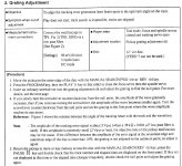
Hi! No, the question is very important. You need DC current for to focus, it depends of the distance of the mirror, the own optics, etc... With DC current you adjust the focus, and with low frecuency, you have to produce a focus-unfocus movement. In this pic, you can see that what I mean.
This draw is not from a CD player laser pickup, but is useful for to show the idea.

When you replace a diode laser, the problem is to adjust the position of the photodetector diode array, this is the main job we must search. For this, we use the astismatic propiery of the laser optic, with this propierty, you can see that if we moves the lens a bit forward(positive V in the graphic), the spot of the laser is converted in a elipse, that only iluminates c and a diodes. If we moves the lens backward(center, 0 v in the graphic), the elipses goes to the center, so is a perfect spot, same light in a-b-c and d diodes. If we give more negative, the spot light is converted in another elipse, that only iluminates b and d diodes.
View attachment 1047266
Comparing A-C and B-D is how Focus Servo works. E and F photodiodes are useful at the beginning, because when you start to adjust, are the first signals to appear.
When you mount the oscilloscopes, amplifier, and all the stuf, the right sinal must be something like that:
https://www.diyaudio.com/community/attachments/img_20211013_185031-jpg.1001283/
This draw is not from a CD player laser pickup, but is useful for to show the idea.
When you replace a diode laser, the problem is to adjust the position of the photodetector diode array, this is the main job we must search. For this, we use the astismatic propiery of the laser optic, with this propierty, you can see that if we moves the lens a bit forward(positive V in the graphic), the spot of the laser is converted in a elipse, that only iluminates c and a diodes. If we moves the lens backward(center, 0 v in the graphic), the elipses goes to the center, so is a perfect spot, same light in a-b-c and d diodes. If we give more negative, the spot light is converted in another elipse, that only iluminates b and d diodes.
View attachment 1047266
Comparing A-C and B-D is how Focus Servo works. E and F photodiodes are useful at the beginning, because when you start to adjust, are the first signals to appear.
When you mount the oscilloscopes, amplifier, and all the stuf, the right sinal must be something like that:
https://www.diyaudio.com/community/attachments/img_20211013_185031-jpg.1001283/
Attachments
Hello pat66,Hi Ruzki,
The schematic I used is the one that Manolomos published and it is the same you used also.
What I added is a SONY CXA1081, it is the IC that can be seen on the board. I'm using only the APC power supply function for the laser diode.
For the power supply I'm using a dual lab power supply but I added on the PCB a LM7815 and a LM7915 with usual filtring.
There is no other filtring on the inputs.
At today I worked on 2 units.
On the first one I only replaced the laser diode. This one is working very well.
On the second one I had to replace the flexible PCB because the original was damaged. That means that I had to desolder the photodiodes array and remonted it on the new PCB. To do that I had to remove the optical bloc from the black plastic frame and it is certainly why now a have to readjust its the position by the mean of the two srews located near the aluminium bloc. This bloc is actualy reading the CD only on the very first tracks.
I wonder how you connected the CXA1081.
Which external components have you used to get the APC working?
Did you use the capacitors between pins CC2 and CC1?
I used to supply my laser diode directly with a certain voltage but I would like to use the CXA1081 instead because I think that I have maybe damaged the laser diode by applying direct power to it.
You may have a schematic or you may could point me in the right direction.
I'd avoid to build a laser power supply. I uses the own CD player laser power supply. Some laser pickup laser power supply are built in. And, if you want to build a laser diode power supply, you must know that usually are N and M laser diode type, P type are rare, so, two(or three) different kind of power supplys.
So, I'd don't worry about this hardware. I'd use its own from a CD player.
But, if you want to build one, I'd chose a design from a early CD, like a Denon DCD-1800, Pioneer P-D70, with transistors and operational amplifiers. And, a 70 or 80ma limiter for to avoid break the laser diode.
So, I'd don't worry about this hardware. I'd use its own from a CD player.
But, if you want to build one, I'd chose a design from a early CD, like a Denon DCD-1800, Pioneer P-D70, with transistors and operational amplifiers. And, a 70 or 80ma limiter for to avoid break the laser diode.
I think that in my case it is not really feasible to use the power supply of the player.
The CD drive is controlled via the main radio and it will be switched off when it gets no valid signal from the CD drive.
CXA1081 is also used in my CD drive to power the laser diode, in fact it would be the same power supply.
Still I´m not sure how basic the circuit of the CXA1081 can be and which state Pins like FOK, TE, FE, FE BIAS need to be in.
Since pat66 used a CXA1081 as well, I hope that he could give me an advise.. or maybe somebody else.
I´m not worried about the APC connection and type of the LASER diode since i got a schematic from the original CD.
- Home
- Source & Line
- Digital Source
- KSS-190A with new laser diode. Applicable for the KSS-151A too.