It seems Jocko Homo who used to frequent these pages before I think getting banned for being so affable
LOL.

actually thermal diffusion caused distortion is visible even in THD distortion frequency sweep plots if not masked by the output stage nonlinearity - if you see a hump in the kHz that goes back down before the typical rise with frequency as loop gain falls, is bigger with heavier load...
of course there are other multitone or discontinuous 'load soak' test signals that give higher resolution, better separation of thermal effects
of course there are other multitone or discontinuous 'load soak' test signals that give higher resolution, better separation of thermal effects
And now you go on about addressing the thermal gradient issue, totally irrelevant to the discussion. My question was, does anyone test for it?
Why? It's frozen in the mask set in the most fundamental sense. You have 8000 die they all are geometrically exactly the same they do the same thing. It was disclosed, what in 1974?, and that was that. I haven't seen a precision amplifier with thermal gull wings in 40 yr. Where do you think the sub-micro per volt DC transfer functions (AOL) under load come from? Any device to device residual is far down in the ppm level.
Last edited:
Yes, it's a BJT input amplifier. The input bias current and current noise are pretty good indicators also.
If not the data sheet! (Although looks like AD doesn't explicitly state what the input transistors are)
Another opamp in the ADA line worth looking at for I/V is the ADA4897 -- low noise, fast-as-fast-can-be (dominant pole compensation all the way out to its 100 MHz UGBW), and similar distortion levels as the 4898. Limited to +/- 5V, but with +/- 2V output goals from the I/V, well within its swing range.
Last edited:
Question: What's best for the input of an I/V opamp, bi-polar or fet??
I'd say FET and the handwaving reason is that FETs don't demodulate RF like bipolars do. Opamps present a nice low impedance to the DAC to allow it to operate optimally but in my experience they do create power supply noise because they're classAB. I suspect CraigBuckingham is on to something when he mentions the DI process - the best sounding opamp I have heard (not in I/V I might add) is a DI process bipolar input one. I have a hunch that IC substrates might be a vehicle for RF noise propagation hence the broad preference in audiophile circles for discretes. Discrete design allows classA operation which is a big reason in my book for going discrete.
I do plan to try a FET input in my classA I/V circuit (currently all bipolar) and see if there's any improvement.
ADA4898, ADI's 'highly linear input' magic
...No degeneration used, but the later multi-tanh input amps get some real benefit at audio frequencies. No PIM in an absolute sense
John, The ADA4898 uses Nathan's spin on the multi-tanh input that we discussed at length. In essence distortion-wise it has the same performance as Barrie's simplest two area ratioed diff-pair circuit (which is public domain). The catch is that the low noise .9nV is preserved here but not in Barrie's circuit, unless the currents are unreasonable.
Nathan's circuit is patented US6963244 so it is public record. Nathan is one of those new young guys I was telling you about from San Jose State. I introduced him to Jim B. but that was somewhat a disaster.
Yes PMA, John please download and read the datasheet, this part is specified down to 100 Ohm RL and with total feedback circuits down to 500 Ohms, and don't forget the multi-tanh input completely removes Barrie's PIM mechanism here it is identically zero.
the best sounding opamp I have heard (not in I/V I might add) is a DI process bipolar input one.
And which op-amp is that?
HA-5222
Thanks for the reply. Looks those have been discoed by Intersil and are long gone.
Did they ever replace it with a comparable part?
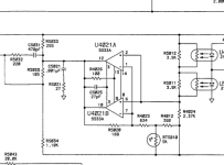
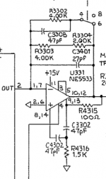
Little bit off topic, how are these NE5533 (dual 5534 in DIP14) paralleling?Each internal nodes are paralleled except a point ,second stage output - third input.Will the third stage Icq and load current properly balance?The second stage gm is well degenerated, but active load and non degenerated third...
The circuits are from tek AA501A and AP System one, so Mr. Bruce Hofer or colleagues may designed them.
The circuits are from tek AA501A and AP System one, so Mr. Bruce Hofer or colleagues may designed them.
Attachments
Last edited:
Why? It's frozen in the mask set in the most fundamental sense. You have 8000 die they all are geometrically exactly the same they do the same thing. It was disclosed, what in 1974?, and that was that. I haven't seen a precision amplifier with thermal gull wings in 40 yr. Where do you think the sub-micro per volt DC transfer functions (AOL) under load come from? Any device to device residual is far down in the ppm level.
Scott, do you remember the articles by Douglas Self regarding amplifier output stages which also covered optimally biasing class A/B output stages?
Interesting technical papers with lots of different output stages and distortion measurements showing how to reduce the trough in the crossover region for minimal crossover distortion.
Thing was, it was all nonsense. He was overlooking other mechanisms which he never mentioned.
I went there, laughed, and never went back. It may measure well, but it sounded like shite.
It made me realise why the industry bragged about high class A levels in A/B designs and why there were so many in that camp and not Self's.
It made me realise why the industry bragged about high class A levels in A/B designs and why there were so many in that camp and not Self's.
PA's are not IC's. I totally agree more than you think in fact I disagree with virtually all I read on "optimum" class A/B biasing, but it is not a battle I choose to fight. Give 'em as much as the heat sinks can stand I say.
To be commercially successful in the real market IC's have a power budget (and we do know how to make completely thermally symmetrical layouts).
once again the 'highly linear input stage' is poorly advertised but is exactly what's needed in I/V to maintain linearity in the face of the mV switching glitches and over the feared settling time dynamics'
the ADA4898 'highly linear input stage' obsoletes any older comparison using ordinary BJT diff pair inputs
just look at the HD3 plots in the DS (the HD2 is likely limited by the power pin location and Class AB output stage )
Just ordered some ADA4898-1 and -2's
Cheers George
Just got the singles JCX from AD, very fast delivery, and put them in for i/v, no oscillations that I can see on my 100mhz scope, but they do run warm/hot. Noticed they can do 150mA max output current!!!! Do they normally run quite warm?
Haven't had the time to listen yet with a AD825 as the output buffer.
Cheers George
Just got the singles JCX from AD, very fast delivery, and put them in for i/v, no oscillations that I can see on my 100mhz scope, but they do run warm/hot. Noticed they can do 150mA max output current!!!! Do they normally run quite warm?
Glad they're working for you. 8 mA idle means that, depending on the rails (+/-15?), you could be dissipating quite a bit through an soic8 package. It'd not be surprising if they're a bit warm.
Glad they're working for you. 8 mA idle means that, depending on the rails (+/-15?), you could be dissipating quite a bit through an soic8 package. It'd not be surprising if they're a bit warm.
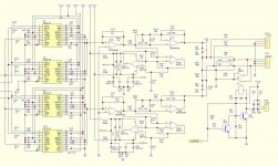
Yep, 15v + and -. here is the full sch of what I'm playing with.
Attachments
I'm assuming you're not replacing the 5532's, but just the 2604's? Probably could recalculate the impedances down as you're throwing away a lot of the noise advantage of the ADA4898. That said, with the 2604's being 10 nV/rtHz, you've got quite a lot of budget, and think the ADA4898 will be around 7 nV/rtHz total noise.
2.7 k in the transimpedance stage is awfully high for a low-noise BJT-input opamp. The beefy nature of the OPS of the ADA4898 isn't being realized either! Not that you should run out to buy a different opamp, but a OPA1642 might have been pretty equivalent to the 4898 in this circuit. Gotta pay attention to the details.
2.7 k in the transimpedance stage is awfully high for a low-noise BJT-input opamp. The beefy nature of the OPS of the ADA4898 isn't being realized either! Not that you should run out to buy a different opamp, but a OPA1642 might have been pretty equivalent to the 4898 in this circuit. Gotta pay attention to the details.
I would try the OPA1642 in both I/V and active filter, but only I/V for the ADA part with the OPA1642 in the active filter position
the ADA4898 Inoise isn't the best with the 2.7 kOhm feedback R but you are going to be limited by the active filter's passives; 10 kOhm Vnoise is higher than the ADA 2.4 pa/rtHz * 2.7 kOhm
the ADA4898 Inoise isn't the best with the 2.7 kOhm feedback R but you are going to be limited by the active filter's passives; 10 kOhm Vnoise is higher than the ADA 2.4 pa/rtHz * 2.7 kOhm
- Status
- This old topic is closed. If you want to reopen this topic, contact a moderator using the "Report Post" button.
- Home
- Source & Line
- Digital Source
- Calling all I/V gurus