I proposed the ADA4898-1 in the AD844 I/V thread some time ago. I was using it as unity gain buffer after step VR and got very good result. I've tried many op amp here and this op amp seems very stable (on a breadboard!). Much better than ADA4897 and ADA4899. Currently, I am using ADA4898-1 on a op-based regulator, and still rock solid even at +-2.5V supply rails.
Looks like you did have problems like me after a few hours.
http://www.diyaudio.com/forums/digital-line-level/227677-using-ad844-i-v-72.html#post4671200
Cheers George
Looks like you did have problems like me after a few hours.
http://www.diyaudio.com/forums/digital-line-level/227677-using-ad844-i-v-72.html#post4671200
Cheers George
Hi George,
I can't remember what happened back then but I'm sure it's not ADA4898-1. The stacked AD844 went well at last, but I chose OPA861 for its simplicity. The 5 stacked AD844s were just too hot, although no oscillation was found.
Poting
Hi,
sounds very much like a oscillation.
The Datasheet recommends generally lower feedback resistor values, as high values increase peaking.
The parallel cap is intended for bandwith limiting, but also to tame peaking/oscillation.
Still though the values used for the DAC are considerably greater than suggested.
Gee guys, when You roll OPAmps do You ever take a look into a datasheet before or is it just `Hey look Mom, it´s got eight legs too!"
I suggest one reads at least page 15 and 16 of the AD-4898s DS.
jauu
Calvin
high feedback R is OK with feedback C, but I think having the feedback C (in 0805 smt) on the DIP adapter would be better
full high speed precautions would involve being on a ground plane with proper supply pin bypass too
another possible hack for DIP adapter use could be to try local 'noise gain' feedback compensation on the adapter
I would try 10x the feedback C in series with ~10 Ohms across the +/- inputs - this can be hacked on by tenting or making a "A frame" of leaning 0805 parts - easiest on the DIP terminal - better on the soic pins - must be done with local feedback C on the adapter
0805 is the smallest I've hand soldered - maybe youth, watchmaker skills would enable even smaller smt parts, build the complete feedback C, noise gain C+R on the SOIC pins
Last edited:
Do you think JCX that with Rf being 2.7kohm and the Cf being 221pf, which gives with my calculations a -3db at 266khz.
If I just raised Cf to 330pf (-3db at 180khz) this could cure my problem? would it harm the performance of the 4898 as an I/V?
This is if I didn't have a faultly 4898 to start with.
If I just raised Cf to 330pf (-3db at 180khz) this could cure my problem? would it harm the performance of the 4898 as an I/V?
This is if I didn't have a faultly 4898 to start with.
Last edited:
If the problem is inadequate High frequency gnding/supply bypass and trace parasitics in the way of the feedback due to using a 65 MHz op amp on a DIP adapter then I doubt anything you do on the main board will save you
hacking, tacking on stuff to the dip adapter with ADA4898 on it may tame the problems - but without a 100 MHz 'scope you can't be sure
on the plus side for hacking, the I/V op amp 2 + inputs should be AC gnd, with 2 widely separated gnd paths from the main pcb to the adapter topside you have a possible low inductance gnd path to work with
what DIP adapter are you using? something like https://www.sparkfun.com/products/13655
I don't know what the whole filter looks like, or what OS ratio, if any
but I would aim for much lower corner frequency – 40 kHz if you believe in generous margin, 18 kHz if you believe in kgrlee, Richard Lee's tests, lit review that limited bandwidth is actually preferred by skilled listeners
Last edited:
"but without a 100 MHz 'scope you can't be sure"
I've got a 100mhz scope with frequency counter, and all I find is around 5mv of 32mhz noise this is very where even on the rails, still haven't found where that's coming from.
But I was thinking last night, the ADA4898-1 has a metal heat pad under it and from what I read it's at negative rail potential, not thinking I did use a spring clamp to hold them in place when I soldered them onto the adaptor board, maybe it has tracks under the 4898 and it shorted after a while when it got warmed up and things expanded?
I'll report back on this.
Cheers George
The 32 MHz could be coupling in from ambient, too. Can you find it elsewhere?
Scott Wurcer wrote some helpful I/V notes in the AD797 datasheet as well, that may be beneficial -- specifically on that parallel feedback C.
Local coupling is of concern -- less ideal to having local bypass on the DIP adapter may be a ceramic cap between the -ve and +ve rails, you just need to push that series inductance down as much as possible. Unfortunately, the pins aren't so favorable for doing this meaningfully.
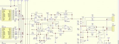
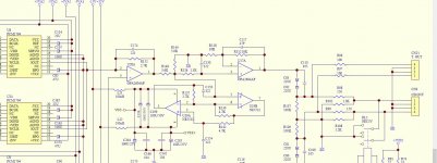
Got the new ADA4898-1's coming. What do you guys think. JCX, DPH, Calvin ect ect???
Change R152 for 1kohm and C174 for 680pf, use smd and connect directly to the ADA4898 pins.
Then to make any gain loss back up
Change R118 from 10kohm to 3.3kohm
Cheers George
Change R152 for 1kohm and C174 for 680pf, use smd and connect directly to the ADA4898 pins.
Then to make any gain loss back up
Change R118 from 10kohm to 3.3kohm
Cheers George
Attachments
curious about the adapter - especially if not using the ADA4898-2 soic-8
again not much you can do on the main PCB will have much effect on stability - I'd just leave the I/V R and gain alone
and you could just add some local feedback C in parallel on the adapter board - plenty of room for more Cf even if you don't want to go below 200 kHz
again not much you can do on the main PCB will have much effect on stability - I'd just leave the I/V R and gain alone
and you could just add some local feedback C in parallel on the adapter board - plenty of room for more Cf even if you don't want to go below 200 kHz
curious about the adapter - especially if not using the ADA4898-2 soic-8
again not much you can do on the main PCB will have much effect on stability - I'd just leave the I/V R and gain alone
and you could just add some local feedback C in parallel on the adapter board - plenty of room for more Cf even if you don't want to go below 200 kHz
Yes I'm using a 2 x soic to dual dip8 adaptor board, but only installing 1 ada4898 on it in no 1 position, as they didn't use the number 2 amp of the opa2604 dip 8 which seems a waist.
If I leave the Rf at 2.7k and Cf at 221pf this is filtering at 227khz?
If I add another 220 to the adaptor board and leave the others as is this will be 110khz filtering?
Cheers George
I get ~270 k and 135 kHz, the later is ~ 0.3 dB down at 20 kHz, really should be inaudible
Sorry, yes that's correct, must have calculated with wrong values.
I think -3db @ 135khz is a good figure, is there any disadvantage for an I/V such as this ADA4898 beauty to be bandwidth limited via the feedback, so long as it not below 20khz?
Cheers George
Last edited:
Don't think it'll be a worry for you but always worth keeping in mind: http://www.ti.com/lit/an/slyt306/slyt306.pdf
My concern wrt oscillations has more to do with bypassing--as JCX says, not much you can do about that on the main board.
My concern wrt oscillations has more to do with bypassing--as JCX says, not much you can do about that on the main board.
I have extra good .47uf right at the socket pins of the + and - rails. Just want not for these new ones to go into oscillation after a few hours again "if" that's what happened before.
I think abraxilito once said to put a small cap from - to + across the rails, can't remember how many uF it was, is this a help??
Cheers George
I think abraxilito once said to put a small cap from - to + across the rails, can't remember how many uF it was, is this a help??
Cheers George
Yes, I think I mentioned that one earlier (probably unclear). Don't need much, purely for HF bypass. 100nf or so, but the leads need to be super short to minimize inductance.
I might be able to put it under the adaptor board straight on the + and - pins.
Has there been any measurements/studies on what this actually does??
Cheers George
I might be able to put it under the adaptor board straight on the + and - pins.
Has there been any measurements/studies on what this actually does??
I've read mixed reviews/opinions whether it does any good or not.
I never place any caps between the voltage rails...just .1uF ceramics right at the power pins.
Has there been any measurements/studies on what this actually does??
It depends on where the output stage currents are flowing. If to 0V then probably its fairly useless might even be harmful. If to one or other of the rails then its the best way to decouple.
- Status
- This old topic is closed. If you want to reopen this topic, contact a moderator using the "Report Post" button.
- Home
- Source & Line
- Digital Source
- Calling all I/V gurus