I wholesale agree with JCX -- apologies that I didn't even look at the filter section's impedances (around U16B/U17A).
The OPA164x a jfet-input opamp with pretty low Vnoise, which, *especially* for the filter section where the network impedances are quite high, will greatly alleviate the current noise concerns. It has more than enough oomph to handle filtering/buffering role, especially considering that it doesn't have to drive a low feedback network.
The ADA4898 in the I/V position (e.g. U27B/U28A) may be a little noiser than the OPA164x, but it *is* a lower distortion/faster part, which is good to have there. You're stuck if you want the output voltage you have, but if you're already aggressively using the volume control, it might benefit from lowering R152/R151 and lowering the I/V gain and buying back some of that very nice noise performance in your ADA4898.
OK lower the gain on the I/V using the 4898, but I'll need to make it up again and a bit more around the output buffer 1641?.
But it's quickly rising output impedance below 1khz, is that a worry? and it's 30mA output current, doesn't this spell out weak bass drive?
Cheers George
But it's quickly rising output impedance below 1khz, is that a worry? and it's 30mA output current, doesn't this spell out weak bass drive?
Cheers George
Attachments
If you need the gain anyhow, don't change the 2k7.
The amount of loop gain over audio bandwidth on the 1642 means the open loop output impedance essentially meaningless (remember what feedback does?). Plus you're driving the input of an amplifier, which will have pretty high impedance, so you really aren't asking for it to dump a huge amount of current. Might matter if you're directly driving a headphone (in which case a buffer is sensible).
The amount of loop gain over audio bandwidth on the 1642 means the open loop output impedance essentially meaningless (remember what feedback does?). Plus you're driving the input of an amplifier, which will have pretty high impedance, so you really aren't asking for it to dump a huge amount of current. Might matter if you're directly driving a headphone (in which case a buffer is sensible).
Another thing I could try as I have all the bits. What do you guys think?
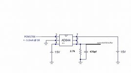
AD844 (tripple stack) feeding the BUF03 Buffer, had good results with this and very low noise on a single PCM1704 a while back but it's major surgery.
But I don't know if the 2 x 1704's will be too much for the 3x AD844's
Cheers George
AD844 (tripple stack) feeding the BUF03 Buffer, had good results with this and very low noise on a single PCM1704 a while back but it's major surgery.
But I don't know if the 2 x 1704's will be too much for the 3x AD844's
Cheers George
Attachments
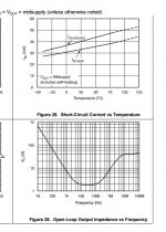
OPA1642 output Z is 'interesting'
the open loop output Z plots looks like a local 'error correction' feedback around the output
getting to single digit Ohms Z is very good compared to most other fet input op amps
as DPH mentions, the high excess loop gain of the op amp global feedback will cover the low frequency output Z
you can calc:
I get ~ 6 milliOhms for the OPA1642 closed loop output Z at low frequencies in the I/V circuit
the open loop output Z plots looks like a local 'error correction' feedback around the output
getting to single digit Ohms Z is very good compared to most other fet input op amps
as DPH mentions, the high excess loop gain of the op amp global feedback will cover the low frequency output Z
you can calc:
the PCM1704 specs 1 kOhm Zout, 2x || and the 2.7 k I/V feedback Z gives ~ 16 dB DC feedback 'noise gain'
and the OPA1642 open loop gain graph shows there's ~ 100 dB open loop gain at 100 Hz
giving ~ 84 dB 'excess loop gain' or 'feedback factor' which divides the ~100 output Z at 100 Hz
and the OPA1642 open loop gain graph shows there's ~ 100 dB open loop gain at 100 Hz
giving ~ 84 dB 'excess loop gain' or 'feedback factor' which divides the ~100 output Z at 100 Hz
I get ~ 6 milliOhms for the OPA1642 closed loop output Z at low frequencies in the I/V circuit
Last edited:
Another thing I could try as I have all the bits. What do you guys think?
AD844 (tripple stack) feeding the BUF03 Buffer, had good results with this and very low noise on a single PCM1704 a while back but it's major surgery.
But I don't know if the 2 x 1704's will be too much for the 3x AD844's
Cheers George
Pretty sure it's going to perform a lot worse.
What are you driving with the OPA1642? It will be fine with just about anything short of headphones as DPH and jcx pointed out.
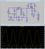
no real circuits were harmed in this sim
a conceptually fun (in sim at least) way to 'unload' the output stage of a op amp in a defined load Z environment is a variation of Sandman's AA scheme
basically a negative impedance converter synthesizes a negative impedance that cancels most of the output current of the attached op amp circuit and all of its feedback and loads
below U1 is approximately a 'I/V' circuit with a bootstrapped ccs output pull down
U2 is the negative impedance converter R2,3 and C3 are scaled approximate models of U1's output total load, R1,4 implement the scale factor
green trace is Vout
yellow is U1 output
red is the current being added to the output by the negative impedance converter circuit
the circuity is trimmed to give good cancellation at 20 kHz, over 90% of the current is supplied by the impedance converter - at lower frequencies the cancellation is only limited by R tolerances
Attachments
Last edited:
Ok, had a listen to the ADA4898-1 in the I/V posistion, and a AD825 in the buffer position, all else is as per the schematic, very very good, I think the ADA4898-1 is my new favourite I/V opamp.
I can hear a little hiss from the speakers, in between tracks un-muted. This is the next to see where that's being generated, next time I scope it, any ideas??
BTW: It's there if the digital domain VC is full up or at zero, and full up is just right for my loudest listening, so gain is right.
Cheers George
Attachments
Well that was short lived, enjoying the sound for a couple of hours, then the right channel dropped to around half level, the ADA4898 was very hot, the left just very warm.
Swapped them around and the same one was still very hot, "maybe faulty" I hope ordered some more. This time will heatsink them with this.
http://au.element14.com/fischer-ele...or-smd-123-c-w/dp/4302163?CMP=i-55c5-00001621
Is there any chance that because I have double 1704's that they can overload the 4898 input with full digital volume?
Cheers George
Well that was short lived, enjoying the sound for a couple of hours, then the right channel dropped to around half level, the ADA4898 was very hot, the left just very warm.
Swapped them around and the same one was still very hot, "maybe faulty" I hope ordered some more.
(...)
Is there any chance that because I have double 1704's that they can overload the 4898 input with full digital volume?
I've had same experience with the ADA4898 in a chinese DAC (15V rails), one channel kept destroying the opamp, changed it several time, at the end I've gave up.
On a CD player (5V rails) it works fine.
It's likely an oscillation problem but I didn't managed to understand why on a single channel only.
If you can convert rails to 5V, though, you may be better served by OPA842 for IV duties.
Sounds like oscillation. Not surprising with this fast of a chip.
Not much different to the AD825 that was in there they were fine, and I checked on the scope, couldn't see anything but 32mhz noise in both cases.
What can be done to compensate the ADA4898-1 a little more, increase C174- C173??
JCX you've played with this chip, any ideas, "maybe I just had a bad one", maybe it got too much heat when soldered to the adaptor board?
Cheers George
I've had same experience with the ADA4898 in a chinese DAC (15V rails), one channel kept destroying the opamp, changed it several time, at the end I've gave up.
On a CD player (5V rails) it works fine.
It's likely an oscillation problem but I didn't managed to understand why on a single channel only.
If you can convert rails to 5V, though, you may be better served by OPA842 for IV duties.
They've got max of + - 18vdc on the data sheet, I'm at 14.99 for both.
Cheers George
Ok, had a listen to the ADA4898-1 in the I/V posistion, and a AD825 in the buffer position, all else is as per the schematic, very very good, I think the ADA4898-1 is my new favourite I/V opamp.
So, George, do you prefer it over AD844 too?
Thanks in advance.
Ouch - no input protection on ADA4898?
PCM1704 output +/-1.2 ma x2 ~ +/-2.4 ma - shouldn't be hard to clamp
AD4898 doesn't give a input protection current rating, only the +/- 1.5 V diff input Vmax spec
maybe worth looking on the ADI discussion forum?
so you may well need a pair of low C diodes across the +/- input
the ADA4894 is also fast enough to make using DIP adapter board problematic - I might try moving the feedback C in 0805 to the adapter
as for heat - 8 ma Iq * 30 Vsupply ~ 0.24 W
looking at a non pwr pad so-8 I see ~ 140 C/W so you shouldn't need heatsinking, only 33 degree C rise from quiescent current
PCM1704 output +/-1.2 ma x2 ~ +/-2.4 ma - shouldn't be hard to clamp
AD4898 doesn't give a input protection current rating, only the +/- 1.5 V diff input Vmax spec
maybe worth looking on the ADI discussion forum?
Q
Does the ADA4898-2 have back to back protection diodes at the input?
I'm afraid that without these diodes we may surpass the +-1.5v differential
mode input voltage at the absolute maximum ratings in an unpowered state.
A
The 4898 doesn’t have back-to-back diodes across the inputs.
The absolute maximum differential voltage of 1.5 V across the inputs is valid
only when the supplies are connected and active. With the supplies floating and
a differential voltage is applied between the two input terminals, current
begins to flow when the differential voltage reaches 0.7 V and reaches about 15
mA when the differential voltage is 1.5 V.
To protect the device from damage in an unpowered state, limit the differential
voltage to 0.7 V. One method to do this is realized by back-to-back diodes
across the input terminals. To ensure stability during normal operation low
capacitance diodes are needed.
so you may well need a pair of low C diodes across the +/- input
the ADA4894 is also fast enough to make using DIP adapter board problematic - I might try moving the feedback C in 0805 to the adapter
as for heat - 8 ma Iq * 30 Vsupply ~ 0.24 W
looking at a non pwr pad so-8 I see ~ 140 C/W so you shouldn't need heatsinking, only 33 degree C rise from quiescent current
Last edited:
So, George, do you prefer it over AD844 too?
Thanks in advance.
Could do, hard to tell two different machines. two different buffers. Don't have the old one with the 3 x AD844 anymore with opa627 buffer some one made an offer I couldn't refuse.
Cheers George
PCM1704 output +/-1.2 ma x2 ~ +/-2.4 ma - shouldn't be hard to clamp
AD4898 doesn't give a input protection current rating, only the +/- 1.5 V diff input Vmax spec
maybe worth looking on the ADI discussion forum?
so you may well need a pair of low C diodes across the +/- input
the ADA4894 is also fast enough to make using DIP adapter board problematic
as for heat - 8 ma Iq * 30 Vsupply ~ 0.24 W
looking at a non pwr pad so-8 I see ~ 140 C/W so you shouldn't need heatsinking, only 33 degree C rise from quiescent current
Hope it was just a faulty one as I have to use adaptor boards, as they don't make dual dip ones only soic single or dual. Dam I was really enjoying it when it was working.
Cheers George
In the mean time while waiting for some more ADA4898-1 to come, I put back the AD827's as the I/V and no problems for two hours sitting at 30c each same 32mhz (5-10mV) noise on the output, it's even on the rails as well, don't know where it's coming from.
Hope it was a dud 4898 we'll see.
Cheers George
Hope it was a dud 4898 we'll see.
Cheers George
I proposed the ADA4898-1 in the AD844 I/V thread some time ago. I was using it as unity gain buffer after step VR and got very good result. I've tried many op amp here and this op amp seems very stable (on a breadboard!). Much better than ADA4897 and ADA4899. Currently, I am using ADA4898-1 on a op-based regulator, and still rock solid even at +-2.5V supply rails.
Last edited:
- Status
- This old topic is closed. If you want to reopen this topic, contact a moderator using the "Report Post" button.
- Home
- Source & Line
- Digital Source
- Calling all I/V gurus