Simple parts upgrade
It somewhat depends on the resolution of your overall system. Can you give us your system profile in terms of components and cables.
Hi guys,
I just got my 205 recently, I am thinking some basic mod such as recaping all caps in the analog board. How much improvement will I get? What should I use? Elna slimic II or Nichicon KZ, or Panasonic FM?
It somewhat depends on the resolution of your overall system. Can you give us your system profile in terms of components and cables.
Why use different capacitors for Front L/R + sub and other channels?
One small question about this modification:......
Why use different capacitors for the front L/R + subwoofer (100uF OSCON) and (10 uF OSCON) for the other channels.
One small question about this modification:......
Why use different capacitors for the front L/R + subwoofer (100uF OSCON) and (10 uF OSCON) for the other channels.
The DAC board of the Oppo UDP 203 has coupling capacitor. ELNA electrolytic capacitors (100uF/ 16v) are used.
Take out those electrolytic capacitors and change to 100uF OSCON together with Wima MKS2 1uF / 63V film capacitor a in parallel for the front left, right and subwoofer channels . Use 10 uF OSCON for other channels .


It somewhat depends on the resolution of your overall system. Can you give us your system profile in terms of components and cables.
I'm still building my system now but I'm looking for good resolution, energy and punch from the oppo mod analog board. Maybe jack of all trade caps will be good. I used slimic II for my 103 but never compare them to other caps so I have no ideas.
Thanks
One small question about this modification:......
Why use different capacitors for the front L/R + subwoofer (100uF OSCON) and (10 uF OSCON) for the other channels.
Smaller value AC coupling caps it may have negative impact over the audio outputted signals. For largest bandwidth and more transparency for the signal, the AC coupling caps it should be at their highest possible value for the available space as the voltage rating, and bypassed with film caps. Also these caps it should be non polarised type.
Using of different (smaller) values for these caps on some of the 7.1 channels setup, is only wrong... There is no any reasons heaving some of these channels "discriminated" so, with lower value for these caps....
Thank you Coris for your awnser.
So it is best to use 100uF OSCON for all the channels.
But now I am doubting this whole simple modification a bit.........
Is it still a good idea to change all the capacitors with the 100uF OSCON together with Wima MKS2 1uF / 63V film capacitors for all channels? will it really give me a (small) improvement?
Or should I use different other capacitors than the suggests ones, what is your advice?.
(I only have a basis technical knowledge, so forgive me my ignorance if my questions look stupid or offensive. I don't want to take any ones advice down. I will have a technical service do the modifications for me, I don't do it myself. I already have a LPM, and a better clock in my 203 and I am looking for a bit more (and relative easy) improvements on the audio-side)
Smaller value AC coupling caps it may have negative impact over the audio outputted signals. For largest bandwidth and more transparency for the signal, the AC coupling caps it should be at their highest possible value for the available space as the voltage rating, and bypassed with film caps. Also these caps it should be non polarised type.
Using of different (smaller) values for these caps on some of the 7.1 channels setup, is only wrong... There is no any reasons heaving some of these channels "discriminated" so, with lower value for these caps....
Mi recommendation is replacing all the AC coupling caps (same value for all), and bypass it with 1-2µ film caps. The main caps should be at least of few hundreds µ (16v rating is fine). Also best is heaving these main caps of non polarised type .
This mod it improve indeed the sound quality. The improvement is only partial, as many other things it should be in place for a real, big improvement. However, it is better than the original SQ...
This mod it improve indeed the sound quality. The improvement is only partial, as many other things it should be in place for a real, big improvement. However, it is better than the original SQ...
Last edited:
Stereo output caps and resistor
Coris is right. Use same treatment for all channels. Existing Silmic II 100uF/16V is an excellent coupling cap. Lots of shootouts on the web where Silmics are ranked at the top. You can up the capacitance by adding extra Silmic in parallel on the underside. But as it is essentially a high pass filter, the 100uF cap already has a very low -3dB cutoff less than 0.1Hz - meaning that all audible signals are passed with minimal attenuation to the preamp/amp you are driving. So upping the cap may not make a huge difference.
On the other hand, adding a bypass cap to the Silmics is much recommended. I'm not a particular fan of WIMA MKS2. Very poorly rated by humblehomemadehifi.com. Minimum quality would be a WIMA MKP10 100V. You can do 1uF or 0.1uF. Not very different. Better bypass would be a Vishay MKP1837 .01uF 100V. Even better would be Cornell Dublier .01uF 3000V, but these are large and I would only do these for stereo board. I have never read compelling comments about the virtues of OSCON for sound quality so cannot comment there.
Another very worthwhile tweak would be to bypass the 100R coupling resistor with say a 10R low noise Mundorf MR5 10ohm on the underside. Inexpensive and nice.
Perhaps change the rectifiers to Schottkys for a couple of bucks while you're at it.
More than that - and you will be making bigger changes of the design type, where Coris is the master.
.Thank you Coris for your awnser.
So it is best to use 100uF OSCON for all the channels.
But now I am doubting this whole simple modification a bit.........
Is it still a good idea to change all the capacitors with the 100uF OSCON together with Wima MKS2 1uF / 63V film capacitors for all channels? will it really give me a (small) improvement?
Coris is right. Use same treatment for all channels. Existing Silmic II 100uF/16V is an excellent coupling cap. Lots of shootouts on the web where Silmics are ranked at the top. You can up the capacitance by adding extra Silmic in parallel on the underside. But as it is essentially a high pass filter, the 100uF cap already has a very low -3dB cutoff less than 0.1Hz - meaning that all audible signals are passed with minimal attenuation to the preamp/amp you are driving. So upping the cap may not make a huge difference.
On the other hand, adding a bypass cap to the Silmics is much recommended. I'm not a particular fan of WIMA MKS2. Very poorly rated by humblehomemadehifi.com. Minimum quality would be a WIMA MKP10 100V. You can do 1uF or 0.1uF. Not very different. Better bypass would be a Vishay MKP1837 .01uF 100V. Even better would be Cornell Dublier .01uF 3000V, but these are large and I would only do these for stereo board. I have never read compelling comments about the virtues of OSCON for sound quality so cannot comment there.
Another very worthwhile tweak would be to bypass the 100R coupling resistor with say a 10R low noise Mundorf MR5 10ohm on the underside. Inexpensive and nice.
Perhaps change the rectifiers to Schottkys for a couple of bucks while you're at it.
More than that - and you will be making bigger changes of the design type, where Coris is the master
.Forgive me my ignorance, and perhaps "stupid" questions....
But could you give me a few brands/types which I could use as good main caps, which are a bit better than the original ones. I don't want to order the wrong ones. Or should I just leave the originals in (like dtossan suggests) and only add the by-pass caps.
(The by-pass caps brand/types are clear to me)
The main caps should be at least of few hundreds µ (16v rating is fine). Also best is heaving these main caps of non polarised type .
Best of all in this field is to just bypass the AC coupling caps with a wire, and use the outputs in DC coupling. As usual it should be there an few mV DC offset, which it should be tolerated by most amp/preamps. At least this is the easiest and cheapest solution. If your preamp/amp it may have coupling caps on its inputs (as most do), then is no reason having a redundant AC coupling into the signal path. A measurement of the DC offset, it should be necessary to confirm the low offset. Measure the DC level before the existing 100µ caps.
If AC coupling should be chosen, then any bigger capacity non polarised caps it should be better than the original ones (bypassed with film caps, of course).
Accordingly by the book and calculation, these AC coupling caps for the frequency range of a audio signal, an 10µ value, or so it should be enough. In fact, as bigger the coupling cap value, as better the sound quality in the low end of the spectre. This is hearable. Not all the time the results of (by the book) calculations it fit with the human perception...
However, in your case, if you can have a DC coupling in your chain, then is the best solution (without any caps).
Last edited:
what caps to use here in oppo 205's analog board ?
Hi Guys.
I just opened my Oppo 205 to measure the caps size.
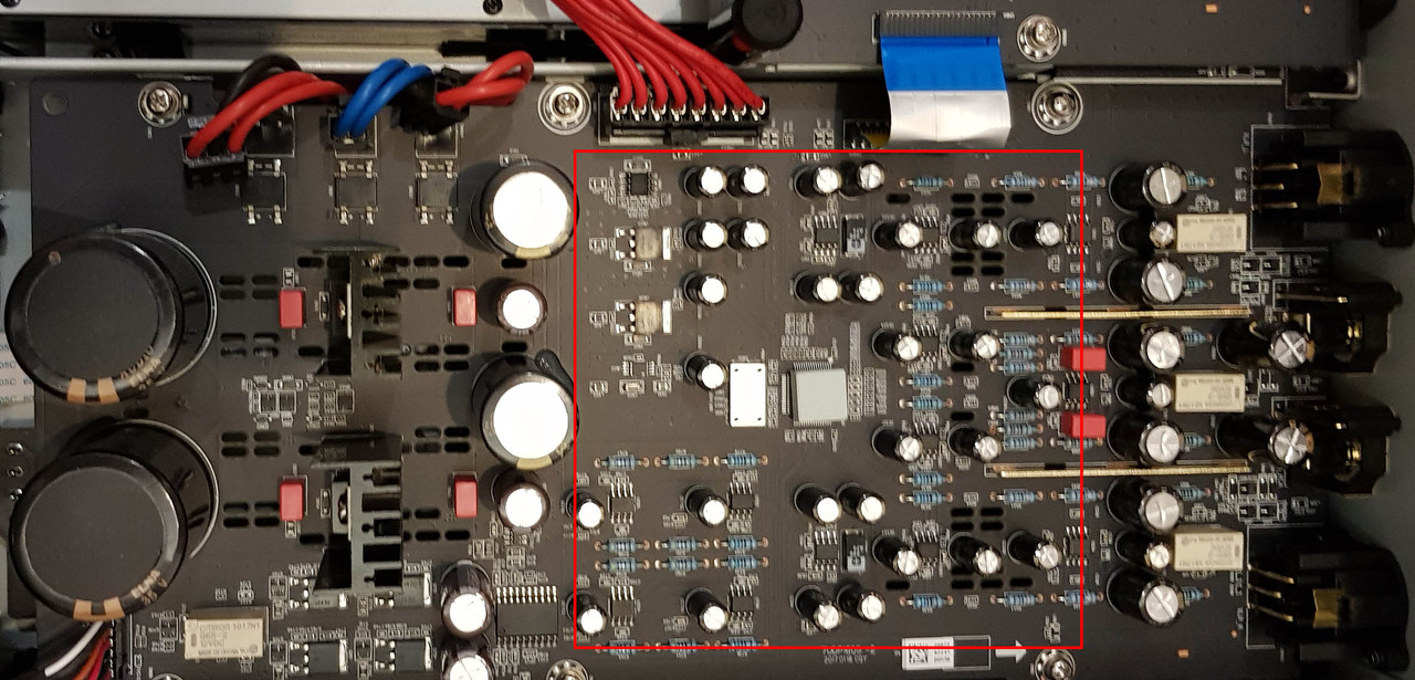
I am planning to recap all caps in analog board, have some plans already but not sure what replacement to use with 29 x 220uf 16v? (see red rectangle in photo)
I was thinking Slimic II or Nichicon KZ but they all 50% bigger in diameter. Later I found out Oscon SP seems to fit well. Can someone give me feedback? Are they the right caps to use?
Thanks

Hi Guys.
I just opened my Oppo 205 to measure the caps size.
I am planning to recap all caps in analog board, have some plans already but not sure what replacement to use with 29 x 220uf 16v? (see red rectangle in photo)
I was thinking Slimic II or Nichicon KZ but they all 50% bigger in diameter. Later I found out Oscon SP seems to fit well. Can someone give me feedback? Are they the right caps to use?
Thanks
Thanks for the information.
I would like my 203 to be compatible with "all" amp/preamps in case I would sell it or buy a other one. So I will change the AC coupling caps for something better and add bypass film caps and hope for a small bit more improvement on the 7.1 analog output.
We will see..........(euhhhh....we will hear)
I would like my 203 to be compatible with "all" amp/preamps in case I would sell it or buy a other one. So I will change the AC coupling caps for something better and add bypass film caps and hope for a small bit more improvement on the 7.1 analog output.
We will see..........(euhhhh....we will hear
)Best of all in this field is to just bypass the AC coupling caps with a wire, and use the outputs in DC coupling. As usual it should be there an few mV DC offset, which it should be tolerated by most amp/preamps. At least this is the easiest and cheapest solution. If your preamp/amp it may have coupling caps on its inputs (as most do), then is no reason having a redundant AC coupling into the signal path. A measurement of the DC offset, it should be necessary to confirm the low offset. Measure the DC level before the existing 100µ caps.
If AC coupling should be chosen, then any bigger capacity non polarised caps it should be better than the original ones (bypassed with film caps, of course).
Accordingly by the book and calculation, these AC coupling caps for the frequency range of a audio signal, an 10µ value, or so it should be enough. In fact, as bigger the coupling cap value, as better the sound quality in the low end of the spectre. This is hearable. Not all the time the results of (by the book) calculations it fit with the human perception...
However, in your case, if you can have a DC coupling in your chain, then is the best solution (without any caps).
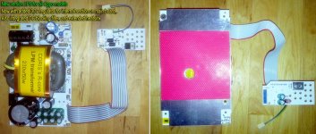
My new version linear power supply (LPS) for Oppo players.
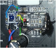
I have integrated the DC blocking filter on board (in an main AC filter compact module), and I have added a 3,3v regulator, which it provide linear power to an internal section inside main board (replacing one of the SMPSes). A modification on main bord is necessary for using the new LPS 3,3v rail. This rail it power a section responsible for optical drive data processing, as for HDMI audio dedicated output (205 model).
The heatsink surface it is extended as well. Some minor PCB design improvements in new version. This last LPS PCB version it perfectly fit for all Oppo models (accordingly populated, and configured).
Attachments
Last edited:
My new version linear power supply (LPS) for Oppo players.
I have integrated the DC blocking filter on board (in an main AC filter compact module), and I have added a 3,3v regulator, which it provide linear power to an internal section inside main board (replacing one of the SMPSes). A modification on main bord is necessary for using the new LPS 3,3v rail. This rail it power a section responsible for optical drive data processing, as for HDMI audio dedicated output (205 model).
The heatsink surface it is extended as well. Some minor PCB design improvements in new version. This last LPS PCB version it perfectly fit for all Oppo models (accordingly populated, and configured).
Nice! Is this the same modification you talked about in post 452, which had a very positiv effect regarding videoplayback ?
The power management in Oppo players is quite sophisticated, and a processor chip it do the job for entire device, including the analogue section as well. For example, all the small SMPS on main board are precisely controlled at power on and off events. There is not the amount of power, the factor which it determine the necessity for control, or not control, but the time sequencing requirements for the so the many different chips, their power input lines, their right time for be up or down, related to their functions into the system.
The added regulator in my last version LPS it is actually integrated into the designed power management, and it provide power which is on/of controlled by the power management controller. I have only exploited the original design, adding this linear power line. In this case and for that section inside the main board, it was possible so.
There is possible also analogue power for the entire digital stage (ideally), but then the power management it should be designed particularly for this purpose.
The main advantage of the local small power SMPSes, is their very fast response at on/off events. Not the case of a analogue PSU.
Last edited:
Hi Coris, I'm thinking of upgrading the Elna 6800uf 35v Caps on the Analog board of 205 to Mundorf 22000uf 40v or 25v MLytic AGs and bypassing with a film cap. My question is ripple current Verses ESR.
The 40v version of the Mundorf has 8.5 Nominal ripple current IR at 105C and 100hz and an ESR value of 9ohm at 100hz.
The 25v version of the Mundorf has 5.4 NRC IR at 105C at 100hz and ESR of 14ohm.
The 63v has 11.2 NRC and 7ohm ESR. which I don't think will fit.
Can you tell me which would be more desirable to use in this area?
Thanks for your future response.
Moto.
Coris, These are my MODs so far. Replaced the output caps with Silmic IIs 470uf 16v, replaced the 100ohm resistor with 10ohm Vishay Z-Foils, bypassed the Silmic IIs with Cornells for output coupling and later I will add another higher value probably 1 or 2uf Film cap as you suggested, just need to find a manageable size, and replaced the main diodes with Shottkys smp’s. Oh and my thanks to you for suggested the 470uf 16v Silmics and thanks to dtossan for the Cornell and Shottky SMP diode information.
Moto
Moto
Last edited:

- Home
- Source & Line
- Digital Source
- Oppo new UDP series players - 203/205 - Discussions, upgrades, modifications