The value of 0,01µ for bypassing the AC coupling caps, it may be too low to give a noticeable improvement. You can keep these caps in place, but a 1-2µ film caps it should also be added, for a better result. Best result is bypassing the caps completely (shorting it - DC coupling).

Stereo Board power section ripple
Hey Coris
Am I reading this correctly - that ripple at opamp from+12V Regulated supply is 48mV?
Is that the level between the 2 orange dashed lines or should we be looking at the main green ripple itself?
I think I cannot see clearly from the image resolution - looks like there are just a few spikes which shoot up, but most of the ripple is 1/3 of the 48mV. Is that correct?
Den
I did some detailed measurements on an original 205 stereo board (analogue power stage)...
Hey Coris
Am I reading this correctly - that ripple at opamp from+12V Regulated supply is 48mV?
Is that the level between the 2 orange dashed lines or should we be looking at the main green ripple itself?
I think I cannot see clearly from the image resolution - looks like there are just a few spikes which shoot up, but most of the ripple is 1/3 of the 48mV. Is that correct?
Den
I think you should download the pictures, to get a better resolution. Here on site it are compressed, I suppose.
The orange pin on my probe is actually the ground. The another one is the active one...
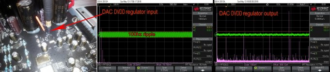
I have measured the ripple at the positive regulator output, and there is just huge. Definitely at the regulator output, the ripple level it should not look like you can see in picture. That is not a normal functional mode for a linear regulator...
Then I have measured on the same rail at the opamp power pin (the positive one). The ripple is quite non existent there. I am not very clear about how it is disappeared... However, the + rail it looks like in the screenshot at the opamp power pin. The spikes to be seen, are digital noises which it come somehow into the analogue power system...
What it is in green on the display center is the normal signal, while the purple one at the display bottom, is the FFT (volt) calculations (illustration) of that signal.
The orange pin on my probe is actually the ground. The another one is the active one...
I have measured the ripple at the positive regulator output, and there is just huge. Definitely at the regulator output, the ripple level it should not look like you can see in picture. That is not a normal functional mode for a linear regulator...
Then I have measured on the same rail at the opamp power pin (the positive one). The ripple is quite non existent there. I am not very clear about how it is disappeared... However, the + rail it looks like in the screenshot at the opamp power pin. The spikes to be seen, are digital noises which it come somehow into the analogue power system...
What it is in green on the display center is the normal signal, while the purple one at the display bottom, is the FFT (volt) calculations (illustration) of that signal.
Last edited:
Last edited:
Good work. So for stock 205 DVDD rail, I see rectifier output has 420mV ripple (at 100Hz because you are in 50Hz country), and regulator output has 44mV ripple.
Yes, it is right. My main AC is 50hz.
44mVpp is an overall level of the noise spectre (Vpp). Please look at the purple (FFT) part of the screen. The settings are on 100µVpp per division. The highest frequency pick in this pictured frequency range is of 700µVpp.
A DC rail covered by such large spectre noises it looks enough bad indeed. We may not forget that here is about a DC power rail connected to (powering) a digital circuit/stage (inside the chip). The noisy digital circuit it will however negatively affect the "cleanness" of a DC power source. So, what is to be seen here, is not very far from normal.
My concern is about the enormous ripple level at the regulator input. A certain ripple level at an linear regulator input is normal as well, but not at such level. This is an indication of a wrong tailored power system. They bet on the regulator capability to filter out the ripple, but in my opinion, such design approach is only wrong. It works, but it not provide quality... Well, average...
Last edited:
1 - 2u suggestions?
Hi Coris, so I can always piggy back a 1 - 2uf film cap, but the problem is having enough room to mount a high quality film this size under the board that is not going to break my budget. So on that note do you have any suggestions on what cap to use, maybe one you have had good results from in the past?
Moto.
The value of 0,01µ for bypassing the AC coupling caps, it may be too low to give a noticeable improvement. You can keep these caps in place, but a 1-2µ film caps it should also be added, for a better result. Best result is bypassing the caps completely (shorting it - DC coupling).
Hi Coris, so I can always piggy back a 1 - 2uf film cap, but the problem is having enough room to mount a high quality film this size under the board that is not going to break my budget. So on that note do you have any suggestions on what cap to use, maybe one you have had good results from in the past?
Moto.
My recommendation is using always SMD film caps for bypassing. The advantages of such components are: small dimensions, no ESI and extremely low ESR, and it can be soldered right on the pads or on the terminals of the main caps. Well, some skils and tools should be in place for using these type caps. One can get the skills by experimenting a little bit...
The SMD film caps are very sensitive to high temperature (are made of plastic film, actually). So the time used for solder their terminals is very critical. If too long time, then the whole cap it will melt altogether, in a nice metal/plastic compound drop. I can go into more details about soldering such components if necessary.
Also soldering together (in parallel) many low value caps, one can get the needed final value. In this case the working voltage of such caps it should be at a minimum of 16v. A 50v working voltage it still be very convenient, providing a good compromise dimensions/price/quality for SMD film caps. For higher voltsage rating, the film SMD caps become bigger, and so easier to be manipulated (well, their price it rise as well...).
Another solution is mounting together (in parallel) 4 x 0,47µ/50v (for an aprox 2µ value) conventional leaded film caps, as Wima or whatever. A such composite cap dimensions it still yet much smaller than a film cap rated few hundreds or thousands volts. There is also a functional advantage when using many paralleled film caps, in case of bypassing a electrolytic one.
Well, some suggestions....
Last edited:
Hi Coris
What's a good schottky bridge replacement for the DF02S bridges on the stereo board?
Den
What's a good schottky bridge replacement for the DF02S bridges on the stereo board?
Den
Hi Den
Well, hard to say precisely... There are lot of such type devices out there. I couldn`t find a right Schottky bridge (as I wanted that time) for these Oppo boards, and I gave up the searching... I decided to build myself the bridges, using discrete components. I have designed some small PCBs, and I plant there the diodes to fit for the application in case. I do it so, so far.
There are some criteria when choosing (Schottky) diodes for rectifying purposes. It have to sustain the needed current, fit for the voltage, and the physical dimensions are also important. The switching speed is not important in this case, as it is not about more than 50hz. The most important parameter is the lowest voltage drop, or what you may see (lowest is better) when you measure it in direct conduction. This is important for ripple figures...
As the forward current rating is higher for a such diode, the lower is the voltage drop on it, when is to be used for a much lower current. A compromise between the forward current figures and the physical dimensions have to be made as well.
At least, using a Schottky diode/bridge is an advantage in itself, because their capability to oppose a less "resistance" in rectifying process (comparing with the usual ones).
Sorry for not a more precise answer....
Schottky rectifier
Thanks Coris
The reason why I asked is because it was decades ago when I played with circuits, well before the days of smds. I see now there are so many smd and microprocessor choices, like kid in candy store. While switching to Schottky is an obvious tweek done by everyone, like upgrading to higher quantity/quality capacitor, I am surprised it’s hard to find Schottky bridge to replace the common DF02S.
What Schottky rectifier did you choose?
It may not be very hard to find a such bridge. I did not insisted too much into this field, as the mentioned my way of doing, I found it more versatile, adaptable for many more applications. Then I did not focus it on this task too much...
I am sure you may find some components to fit, if you will do some efforts in this direction. Maybe I will do it one day myself too... However, it is not my priority right now...
For stereo board in Oppo I use 4A/40v Schottky diodes. For LPM I use 10A/45v diodes, of a very good quality (there the voltage drop on the rectifying diodes is quite critical).
These type of diodes it have positive impact over the ripple level (compared with the classical ones), but most important in this field are the filtering capacities used after the bridges. Well, a good tailored transformer is also very important.
The rectifying Schottky diodes are only a part of the improvement process, but taking it alone, it mai not bring dramatic results.
Replacing only these diodes into a power system, it could happen that, due to their parameters, the ripple it get lower with the rest of the existing components. This it could be noticeable in the final resulting audio signal, outputted by the device in case. So, the one may conclude that the diode it improve the sound. This is not entirely true... An improvement process, it may be seen as a complex system, where parts, factors and components it contribute each in their field, to the final overall result.
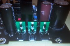
This (bellow picture) is how I am doing right now...
I am sure you may find some components to fit, if you will do some efforts in this direction. Maybe I will do it one day myself too... However, it is not my priority right now...
For stereo board in Oppo I use 4A/40v Schottky diodes. For LPM I use 10A/45v diodes, of a very good quality (there the voltage drop on the rectifying diodes is quite critical).
These type of diodes it have positive impact over the ripple level (compared with the classical ones), but most important in this field are the filtering capacities used after the bridges. Well, a good tailored transformer is also very important.
The rectifying Schottky diodes are only a part of the improvement process, but taking it alone, it mai not bring dramatic results.
Replacing only these diodes into a power system, it could happen that, due to their parameters, the ripple it get lower with the rest of the existing components. This it could be noticeable in the final resulting audio signal, outputted by the device in case. So, the one may conclude that the diode it improve the sound. This is not entirely true... An improvement process, it may be seen as a complex system, where parts, factors and components it contribute each in their field, to the final overall result.
This (bellow picture) is how I am doing right now...
Attachments
Last edited:
I have used SiC Shottkys with good results - I have used the followings in 105 and 205 respectively:
http://www.farnell.com/datasheets/6...15.1234529841.1526719697-422525255.1526719697
http://www.ttelectronics.com/themes/ttelectronics/datasheets/semiconductors/sic/SML010FBDH12.pdf
http://www.farnell.com/datasheets/6...15.1234529841.1526719697-422525255.1526719697
http://www.ttelectronics.com/themes/ttelectronics/datasheets/semiconductors/sic/SML010FBDH12.pdf
When about rectifying, all the diodes (which it fit for the current and voltages for the application) are good. No matter it are Schottky or whatever.
The clue, when about improving ripple figures for the application (as thermal dissipation), is using diodes with lowest "Forward Voltage VF". The Schottky type diodes are far better in this area. However, are such Schottky rectifier or bridges which are not so good for the job in a field or another. A Schottky diode/bridge made for industrial applications, may not fit very well for Oppo boards, or something like this. Well, it will do the job, but maybe more similar to the original one...
There is a difference (ripple result point of view) in between an Schottky device with an "Forward Voltage VF" of 1,5v, and one with this parameter of 300mV or so... Schottky bridges are not so easy to be found for so low forward voltage, while discrete diodes are easier to find it. I guided myself following this parameter in my choosing the right (in my opinion) component for my applications.
There are some other factors as well, which may decide finally for one or another component (price, dimensions, availability, etc).
105 original Stereo board diodes?
Hi I had replaced the diodes to Schottkys on my OPPO 105 on the Stereo board, I want to put the Originals back before I sell this player, can you please tell me the specs of the originals. Thanks in advance 🙂. Moto
When about rectifying, all the diodes (which it fit for the current and voltages for the application) are good. No matter it are Schottky or whatever.
The clue, when about improving ripple figures for the application (as thermal dissipation), is using diodes with lowest "Forward Voltage VF". The Schottky type diodes are far better in this area. However, are such Schottky rectifier or bridges which are not so good for the job in a field or another. A Schottky diode/bridge made for industrial applications, may not fit very well for Oppo boards, or something like this. Well, it will do the job, but maybe more similar to the original one...
There is a difference (ripple result point of view) in between an Schottky device with an "Forward Voltage VF" of 1,5v, and one with this parameter of 300mV or so... Schottky bridges are not so easy to be found for so low forward voltage, while discrete diodes are easier to find it. I guided myself following this parameter in my choosing the right (in my opinion) component for my applications.
There are some other factors as well, which may decide finally for one or another component (price, dimensions, availability, etc).
Hi I had replaced the diodes to Schottkys on my OPPO 105 on the Stereo board, I want to put the Originals back before I sell this player, can you please tell me the specs of the originals. Thanks in advance 🙂. Moto
Schottky for Stereo Board
Thanks Coris for your advice re Schottky. I agree lower VF forward voltage drop (and low IR reverse leakage current) are important to get lower ripple and good efficiency. The original DF02S bridge is only rated for 1.5A, but high 1.1VF.
For the +/-12V rails, I would go for discrete diodes (as I am thinking of using 4-pole Jensen audio caps as resevoir). A quick search in Digikey for 40V, up to 5A gave me 2 Schottky choices:
497-6588-1-ND. $0.73. VF= 500mV. IR 200µA. STMicro.
SB540-E3/54GICT-ND $0.64. VF= 480mV. IR 500µA. Vishay.
The STMicro diode has lower IR reverse leakage current thus lower heat, but at 12V, we are talking about a tiny .0024W of heat.
The Vishay has slightly better VF – about 20mV less voltage drop.
There’s no need to go for a lower current diode as I have not found ones with better VF and VR. So I suppose either diodes would do.
For the 5V rails, I would go for smd mount Schottky bridge. Found this:
CBRSDSH2-40TR13-CT-ND. 40V. 2A. $1.25 VF= 450mV. IR= 70µA. This bridge has roughly same footprint as the original DF02S bridge.
Above Schottkys all give ultrafast and soft recovery, thus lower noise and faster response as current demands swing with the music. Hopefully the 0.6V increased voltage supplied to the regulators will not cause worrying stress.
All comments welcome 🙂
Your chosen diodes are very good for this application. You can very well use these components for bridges on all the power rails.
The heat dissipation parameter for the diodes it is really not important here, as the currents which goes through it are quite small (comparing with their ratings). For these power rails the diodes get never even warm.... The diodes thermal dissipation it become important at many ampere currents.
In case of this Oppo device, a larger current is on 6v power rails, and less on +/-12v ones. _The +12v rail it use a little bit more current, than -12v one, as it power the AVCC lines for DAC, and the relays as well.
- Home
- Source & Line
- Digital Source
- Oppo new UDP series players - 203/205 - Discussions, upgrades, modifications