Anybody have access to the udp-203 service manual?
Oppo service manuals do exist, but we have never been allowed to see them.
I don't think it is something you can explain or quantify, a bit like using Schottkys on 50/60 Hz - this is an extract from a conversation from Paul McGowan of PS Audio in the Stereophile:
"What do you think a larger transformer is doing [that a smaller one wouldn't?]?
"I can't measure it, so this is purely speculative, but I think it's lowering the output impedance that's going to the circuit. When you demand current from a device—in other words, an output transistor—there is a tendency for the device to sag a bit. You can't really measure it, but every time I've taken a power supply and lowered its output impedance, the sound has improved dramatically. The only thing I can attribute this to is low DC resistance.' "
Sounds like complete BS to me. If he attributes it to low DC resistance then that's easily measured. People who don't know any better still get off on huge toroids. "Must be good!"
I would like to know what the second clock on the top of the 203 main board is for
and how many Mhz please?
and how many Mhz please?
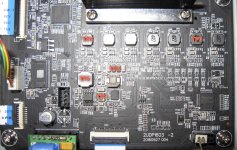
It is a 12Mhz resonator which it clock the chip beside (power management, and other functions controller).
Who copied who?
There was and is quite known that these two producers it had/have very similar design and buildings for their (UHD) players.
I think we may not be so disappointed about Oppo getting out of the competition in this field.
The experienced Oppo modders may easily switch on Cambridge devices. Lot of interesting things to be done there as well. Particularly for their chosen same SMPS solution.
I presume opening a dedicated Cambridge thread very soon... CXU-10 is indeed an interesting device (I guess quite good after improvements)...😉
However, Oppo UDP 205 (as 105 model as well) still remain in my opinion, quite unique, as a very high quality potent hardware...
Attachments
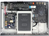

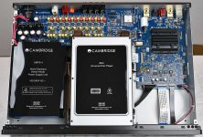
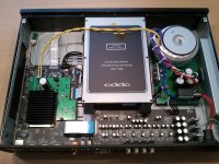
I believe that the Cambridge Audio CXUHD is based on the OPPO 203. The transport and main board are identical. When OPPO stop making universal disk players, companies like Cambridge Audio and PS Audio will have to find an alternative base unit to use as a transport. OPPO sales quantities will be far greater than the number of transport kits sold to OEM manufacturers like Cambridge Audio, so to continue manufacturing for OEMs would not be cost effective.
Simlic bypass cap placement on top of board at resitor points?
Hi Coris, I'm going to be replacing the Wima bypass caps that I soldered on the pads under the board across the Simics with Polypropylene type, they run about 3.4cm x 1cm, can I attach them to the top of the board at the points on the resistors in the picture above instead? I'm not sure If I will have room on the bottom of the board. I have the UDP-205.
Thanks for your future answer, appreciate it.
Moto.
I have available the AC/DC selector for those interested. Please PM me.
Concerning the resistor on the signal path after the AC coupling caps, I recommend to keep it in place, even thought its value it can be reduced.
For those who may want to try (wire) bypassing the AC coupling caps, without removing the caps, or even not dismounting the board, I suggest connecting together the marked points (green circles) on the picture hereby. The same for those who may want using my selector.
For a quality AC coupling, the original caps it should be replaced with non polarised ones, as bypassed with some film 1-2µF caps. If you are sure your preamp/amp it is AC coupled on its inputs (caps or transformer), then wire bypassing is the best choice.
Hi Coris, I'm going to be replacing the Wima bypass caps that I soldered on the pads under the board across the Simics with Polypropylene type, they run about 3.4cm x 1cm, can I attach them to the top of the board at the points on the resistors in the picture above instead? I'm not sure If I will have room on the bottom of the board. I have the UDP-205.
Thanks for your future answer, appreciate it.
Moto.
Hi Moto
I appreciate as enough space under the board. Well, you should dismount the board in this case, to test for your caps dimensions. Another advantage placing the components on board downside is the ground plane in between. I think is better if you may do it so for added components. Please remember that is not necessary high voltage rating for that bypass caps. 50v is more than enough for such caps. So, their dimensions become quite small.
If you may need a guidance for dismounting the device, please watch my video here: YouTube
Last edited:
Stereo Board power section ripple
My improvements so far, for the analogue power stage of 205.
Massive primary filtering capacity. Replaced the original rectifier diodes, with Schottky. Replaced the original +/- regulators with LM2991/2941, mounted on a new designed module. Added pre regulators for DAC power rails: one regulator for the digital DAC power rails, and one regulator dedicated to the analogue power rails (AvccL/R).
Hi Coris
Very impressive work on the power section. You mentioned seeing 200mV ripple at the +/- section and 350mV at the 6.3V section before regulator in the original Oppo 205.
I imagine ripple or noise after regulator is more interesting!
Do you have any measurement of ripple or noise improvement after your mod?
Den
I will do some more measurements soon, as I have right now a 205 on my bench.
I just found out a new improvement for all Oppo devices: providing linear power to a part of the inside digital stage (optical drive processor, SAW oscillator for HDMI audio dedicated output, as some other circuits on digital board). Preliminary results for discs playback (video) is just amazing.
The ideal for an unbelievable quality result it may be a full linear power for all digital chips/components (on digital board). Well, this is not possible, because a lot of heat dissipation. However, it is possible a partial analogue powering, as LPS at the digital board main power input, instead of the original SMPS, and now linear power for one of the 3,3v rails, for an important section of the the digital stage. I only have to find a solution to lower the heat dissipation.
The big problem when eventually replacing all the small DC/DC converters (SMPS), with linear regulators on the digital board, is the power management necessary for power up/down sequences. However, I found a way to use analogue power for a part of the digital system, without disturbing the power management. I have not yet tested the audio, but the picture is only impressive, with this power rail improvement.
This is add on I2s data streaming card for OPPO 203/103(D) blu ray payer : final version.
All beta testers are pleasded with sonic improvements and perfect matching.
PS audio digital audio DAC device etc can be recived I2S signal through the HDMI terminal .
With this, all digital audio signal with the purest state can be output to the outside of OPPO BD player.
Moreover, digital signals can be transmitted even when playing SACD or DSD files. (Can not be transmitted by a normal SPDIF format )
Currently, there are no standards for transmitting i2S signals, but many manufacturers follow the PSAudio standard. This specification uses the HDMI terminal physically (not the HDMI transmission standard).
Surprise Surprise Surprise
Well here is the Thing, In order to power the femto clock or any of the clocks from Jae Hong sales you would need to purchase the LPM with extra power to the clocks. If you purchase his LPM listed on his site first before you decided to use one of his clocks well your screwed, see the LPM listed on his site does not have the extra leads to power the clock. You would need to purchase a whole new LPM from him and sell your original, or find another way to power the clocks.😡
Have anyone tried femto clock from Jae Hong here?
thanks
Well here is the Thing, In order to power the femto clock or any of the clocks from Jae Hong sales you would need to purchase the LPM with extra power to the clocks. If you purchase his LPM listed on his site first before you decided to use one of his clocks well your screwed, see the LPM listed on his site does not have the extra leads to power the clock. You would need to purchase a whole new LPM from him and sell your original, or find another way to power the clocks.😡
Yes, I had the same problem... ordered a LPM from Jae Hong Lee, really liked it and after a year or so I decided I wanted to also upgrade the clocks. But sadly enough I had to also order a new LPM with the extra 4.5v output. He kinda should mention this more clearly on his webshop. But he did give me a small discount on the second LPM and I sold my other one. So in total it did not cost me that much more, but it did take some time and energy to arrange things.
But all and all I do like the modifications, so at the end it all worked out....😀
But all and all I do like the modifications, so at the end it all worked out....😀
Well here is the Thing, In order to power the femto clock or any of the clocks from Jae Hong sales you would need to purchase the LPM with extra power to the clocks. If you purchase his LPM listed on his site first before you decided to use one of his clocks well your screwed, see the LPM listed on his site does not have the extra leads to power the clock. You would need to purchase a whole new LPM from him and sell your original, or find another way to power the clocks.😡
Attachments
I think it may not be a good idea using that 5v power rail inside the main board.
That PSU (actually a SMPS) it was designed to deliver the necessary power for the circuits on board, and it may not work (at least well), if it will be overloaded, with an additional device. If that SMPS is overloaded it will worse at once its parameters, it will generate lot of more HF noises, and its protection mechanism it will shut it down (if its load is in excess than it was designed to be). Powering this way that clock system based on OXCO (using the on board 5v rail), if the small SMPS it will accept it, it will overload the LPM itself, and the heat dissipation it will increase.
That type clock system the above posts refer to, it use quite much power. This device it need a dedicated PSU.
At least, even that OCXO device it apparently works for these players, I am enough critical to such approach. The OXCO it use many hundreds mA at start up, and it need at least a half an hour to get into its designed parameters. Then the constant temperature system it use enough much power to maintain the device at that high temperature. That clock board including OXCO is not designed to start up in the same time with the player, but is maintained always powered (avoiding so the lot of energy used at its own start up). In this way the clock signal is always present at its output, and at the main processor input. This, while the processor it is not powered... This is only wrong, and in my opinion, far from a professional way of doing modern electronic design.
However, the main processor it never need all that clock precision over long period of time (which an OXCO is designed for and it can provide) to work at high performance parameters. Another parameters of a clock signal are important in this case, and the quality of the power used for such device is crucial. Using OXCO in this place is only inadequate.
However, a clocking device it should never be powered from a SMPS source...
Last edited:
I did some detailed measurements on an original 205 stereo board (analogue power stage). It will come here the results. This is the first episode, of the serial...😉. To be continued (quite interesting things).
I will improve this board, and I will do again the same measurements. We shall see what happen...
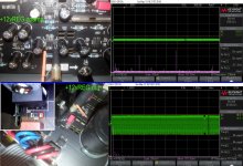
By the way (a bad news), the headphone output it oscillate in Mhz range. I measured it first on my modified board, and I thought it was something wrong with my way of doing, improving this stage. However, I was not very sure about this explanation, as I found the oscillations right at the TPA6120 chip output. I wanted a confirmation, before going out with this information. As I have done the measurement on a new original board, I can confirm now this statement.
It happen only with this last model, as the 105 had not such problems. This is a PCB design fault. It is known that a such fault it can produce HF oscillations out of this chip. I will publish shortly the screenshots.
However, on a stock device, this HP output it provide best listening quality (in my opinion). I used it connected to the amp.
I will improve this board, and I will do again the same measurements. We shall see what happen...
By the way (a bad news), the headphone output it oscillate in Mhz range. I measured it first on my modified board, and I thought it was something wrong with my way of doing, improving this stage. However, I was not very sure about this explanation, as I found the oscillations right at the TPA6120 chip output. I wanted a confirmation, before going out with this information. As I have done the measurement on a new original board, I can confirm now this statement.
It happen only with this last model, as the 105 had not such problems. This is a PCB design fault. It is known that a such fault it can produce HF oscillations out of this chip. I will publish shortly the screenshots.
However, on a stock device, this HP output it provide best listening quality (in my opinion). I used it connected to the amp.
Attachments
Last edited:
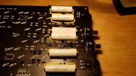
Updated bypas Caps from Wima to Cornell.
I originally replaced the output caps of the 205 Stereo board with Silmic II 16v 470 uf, and bypass with Wima MKS2 1uF/63V. Well I removed the Wima's and replaced them with Cornell-Dublier 940C .01uF/3000V polypropylene film Caps.
Have not come to any conclusion as to changes in sound quality yet, need to give them some burn in.
Mark
Attachments

Last edited:
- Home
- Source & Line
- Digital Source
- Oppo new UDP series players - 203/205 - Discussions, upgrades, modifications