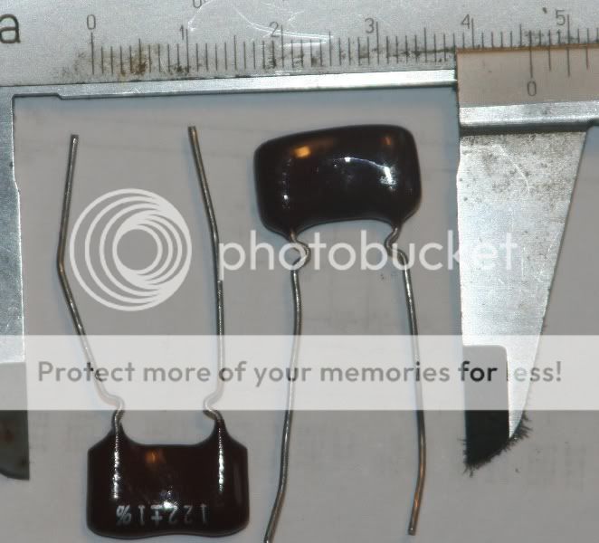
Got the Silver Micas today, do I solder them directly on to the chip (top side PCB) or to the pins on the bottom of the PCB?:
Just a quick question, this cap is to be left in there later on when I get the clock 11.2896Mhz /2 /4 ?
DEM cap has nothing to do w external clock? Or will I have to de-solder it later?
I think those caps are 1200pf!
I don't think you can get 122pf the closest is 120pf which would be marked as 121. Google capacitor value markings ;(
I think those caps are 1200pf!
I don't think you can get 122pf the closest is 120pf which would be marked as 121. Google capacitor value markings ;(
He has proffesional equipment(I had to double check the values with him) and they are 122pF (actually as close as he could get amongst 20pcs of 122pF 1% silver micas he had).
He also said that there are silver micas marked 348, and that the marking you're reffering to is for modern film caps and not for these.
He also pointed to this page explaining markings of silver micas.
Something that may help troubleshoot your 317 regs.
Using The LM317T To Regulate Voltage - Electric Circuit
You are replacing R2 with LED's in your circuit. If its not working, go back to a variable resistor and see if it starts regulating. If it still doesn't, there is something wrong. I think the way the 317 works, is that it always wants to see 1.25v on the adjust pin. If the divider circuit on its own sets it low, the device will raise the output until it see 1.25v again and visa versa.
With respect to the mica caps, if they've been measured then you know they are the right value")
Using The LM317T To Regulate Voltage - Electric Circuit
You are replacing R2 with LED's in your circuit. If its not working, go back to a variable resistor and see if it starts regulating. If it still doesn't, there is something wrong. I think the way the 317 works, is that it always wants to see 1.25v on the adjust pin. If the divider circuit on its own sets it low, the device will raise the output until it see 1.25v again and visa versa.
With respect to the mica caps, if they've been measured then you know they are the right value
Last edited:
Something that may help troubleshoot your 317 regs.
Using The LM317T To Regulate Voltage - Electric Circuit
It explains the standard resistive voltage divider used to set the voltage on the sense pin of the 317.
You are replacing R2 with LED's in your circuit. If its not working, go back to a variable resistor and see if it starts regulating. If it still doesn't, there is something wrong.
With respect to the mica caps, if they've been measured then you know they are the right value
Thanks, I'll have a good long look at that link
Yes, I had to ask him about the caps(double check), and they are meassured(he works for an audio company and has access to proffesional equipment).
Just to further correct.....obviously struggling to type as fast as I'm thinking today!!!
from the on-semi 317 application notes
"The LM317L wants to see 1.25 V between its VOUT pin
and the Vadj pin, and it will do whatever it can to keep that
voltage differential between them."
When you read back my last post, it suggests that the 1.25v is relative to gnd....which its not!!!
from the on-semi 317 application notes
"The LM317L wants to see 1.25 V between its VOUT pin
and the Vadj pin, and it will do whatever it can to keep that
voltage differential between them."
When you read back my last post, it suggests that the 1.25v is relative to gnd....which its not!!!
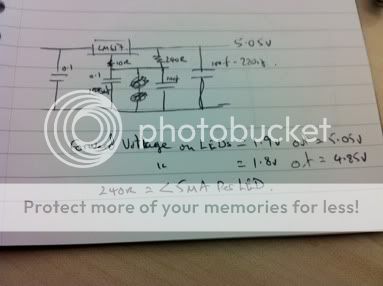
Just drew this to get the LED stuff straight in my head.
You need to make sure the forward voltage across each led is about 1.8v and use 2. You add the led forward voltage to 1.25 and that is the output voltage. 1.8 + 1.8 + 1.25 = 4.85v
You need to make sure the forward voltage across each led is about 1.8v and use 2. You add the led forward voltage to 1.25 and that is the output voltage. 1.8 + 1.8 + 1.25 = 4.85v
An externally hosted image should be here but it was not working when we last tested it.
Just to further correct.....obviously struggling to type as fast as I'm thinking today!!!
from the on-semi 317 application notes
"The LM317L wants to see 1.25 V between its VOUT pin
and the Vadj pin, and it will do whatever it can to keep that
voltage differential between them."
When you read back my last post, it suggests that the 1.25v is relative to gnd....which its not!!!
If I use resistors to set the Vout, what can I do to lower noise levels?
Already have 4 LED's and alot of diodes, filmcaps etc...
Just drew this to get the LED stuff straight in my head.
You need to make sure the forward voltage across each led is about 1.8v and use 2. You add the led forward voltage to 1.25 and that is the output voltage. 1.8 + 1.8 + 1.25 = 4.85v
An externally hosted image should be here but it was not working when we last tested it.
I'll look at that when I get home, thanks!
If I use resistors to set the Vout, what can I do to lower noise levels?
Already have 4 LED's and alot of diodes, filmcaps etc...
You can't!!! That's the point of using LED's or low noise VRefs in the design!!
Just drew this to get the LED stuff straight in my head.
You need to make sure the forward voltage across each led is about 1.8v and use 2. You add the led forward voltage to 1.25 and that is the output voltage. 1.8 + 1.8 + 1.25 = 4.85v
An externally hosted image should be here but it was not working when we last tested it.
Any chance to get a higher res pic or more of a close up pic?
According to specs my LED's are:
2,3+2,3+1,25=6,25V
I guess I'll have to get some new ones then.
Uf = 2.3V
If = 20mA (max 30mA)
~1000mcd
2,3+2,3+1,25=6,25V
I guess I'll have to get some new ones then.
Last edited:
In this schematic I used the LED's are pointed to GND
In yours they seem to be pointed to the pos rail
Is that the problem with the reg I built, LED's pointed to GND?
An externally hosted image should be here but it was not working when we last tested it.
In yours they seem to be pointed to the pos rail
Is that the problem with the reg I built, LED's pointed to GND?
According to specs my LED's are:
2,3+2,3+1,25=6,25V
I guess I'll have to get some new ones then.
My bad, that's 2,3+2,3+1,25=5,85V
Found the following green LED's:
1. 5mm 3,6...4V forward 30mA. Can I use one of these instead of two(1,8 or 1,9) in the schematic, and what does the *3,6...4V* mean? No go?
This one
2. 7,62x7,62mm(more then 2 leads...how to connect?) 3,9V forward(30mA) would give 5,15V, too much? This one
3. 10mm 3,5V typ/4V max. 30mA (3,5+1,25 gives 4,75...too low?)
4. 3mm 3,6V 20mA. No other specs found on sales site
5. 3mm 525nm 3.6V 20mA 7500 mcd
You can't!!! That's the point of using LED's or low noise VRefs in the design!!
Ok, looking around for suitable LED's
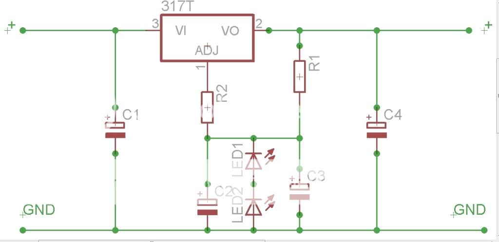
Tried to make a schematic of the one you drew UV101.
Is this correct? BOM for it?
Steady on!!!! This is theoretical and I can already see a mistake!!!!!
R2 & C2 are performing the function of an RC filter on the supply to the adj pin on the reg in an attempt to further reduce noise. I think that R2 needs to be before the cap C2.
The sum of the forward voltages of the LED's needs to be close to 3.75v as any deviation will effect the regulator output. As long as they are +/- 0.2v, I would suggest that would be acceptable.
The current through the LED's will be set by R1. The suggestion from the 317 datasheet was 240r-1k (I think) so closer the the lower figure is preferable in my previous calculations, I think I worked out the current to be approx 5mA.
I would select a some suitable LED's and then just build it to try! its only a few inexpensive components! Also, get dummy load like a small lamp ;-) and make sure you test it before you connect it to the player.
I'm fortunate enough to have a bench PSU meaning I can supply anything from a few mV up to 30v DC to what I'm building. Obviously this is very useful when testing that a regulator is actually regulating! If the output is 5v with an 8v supply and still 5v with a 30v supply, you can pretty much safely say the reg is working!!!
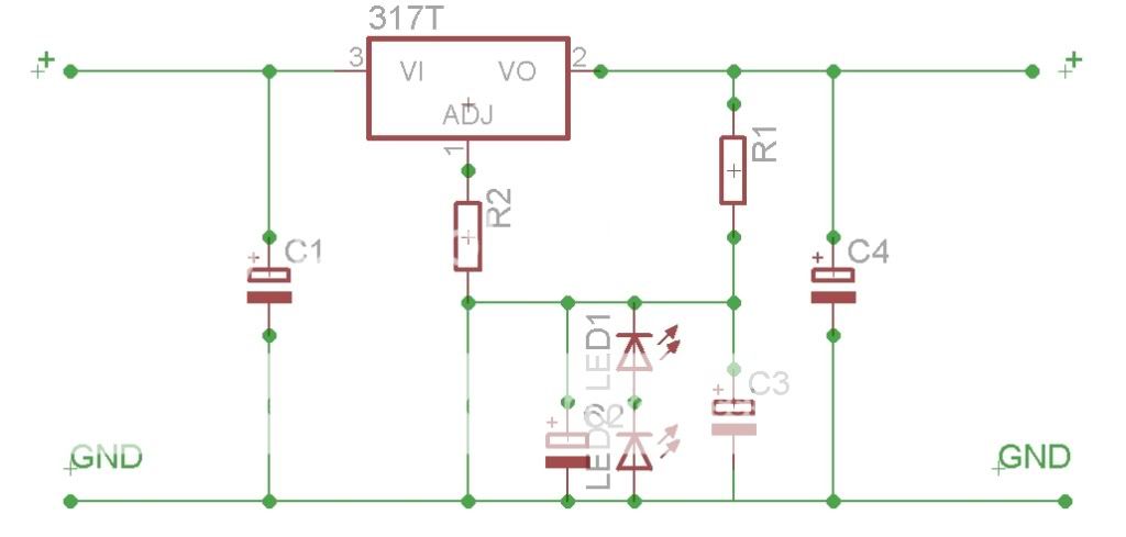
3,6V LED falls within +/- 0,2V of 3,75V, should work? R2 before C2, like this?Steady on!!!! This is theoretical and I can already see a mistake!!!!! R2 & C2 are performing the function of an RC filter on the supply to the adj pin on the reg in an attempt to further reduce noise. I think that R2 needs to be before the cap C2. The sum of the forward voltages of the LED's needs to be close to 3.75v as any deviation will effect the regulator output. As long as they are +/- 0.2v, I would suggest that would be acceptable. The current through the LED's will be set by R1. The suggestion from the 317 datasheet was 240r-1k (I think) so closer the the lower figure is preferable in my previous calculations, I think I worked out the current to be approx 5mA. I would select a some suitable LED's and then just build it to try! its only a few inexpensive components! Also, get dummy load like a small lamp ;-) and make sure you test it before you connect it to the player. I'm fortunate enough to have a bench PSU meaning I can supply anything from a few mV up to 30v DC to what I'm building. Obviously this is very useful when testing that a regulator is actually regulating! If the output is 5v with an 8v supply and still 5v with a 30v supply, you can pretty much safely say the reg is working!!!
- Status
- This old topic is closed. If you want to reopen this topic, contact a moderator using the "Report Post" button.
- Home
- Source & Line
- Digital Source
- Marantz CD-50 and CD-60, TDA1541, CDM4/19