Hi all!
I have had quite a lot of experience with portable speaker design and Bluetooth modules from Qualcomm. I worked with CSR chips, for example, CSR64215 and I didn’t get any problem with programming this chip. Moreover, we have a great thread on this forum with a lot of useful information: CSR8675 programming guide w. software and tons of CSR info
On the market, we have new Qualcomm chips QCCXXXX and the approach of programming not the same with CSR modules. As far as I know, the last chip that supports CSR programming process is QCC3008.
And new chips have features:
These chips have DSP Kalimba and that gives the opportunity to set up audio how I want, make limiter, EQ, bass booster, etc.
I know that this DSP not so powerful as, for example, ADAU1701, but that makes my project chipper using only one chip for wireless connection, DAC and DSP.
QCC5125 and QCC3034\QCC3031 have the same programming approach. For programming those modules, we have two ways. First, we need special programming expensive board. Second, programming with USB.
I found ADK for QCC3031 on the thread that I write above, thanks a lot @ErikDIY for that. I tried to connect this chip to a USB, but I didn’t get any success.
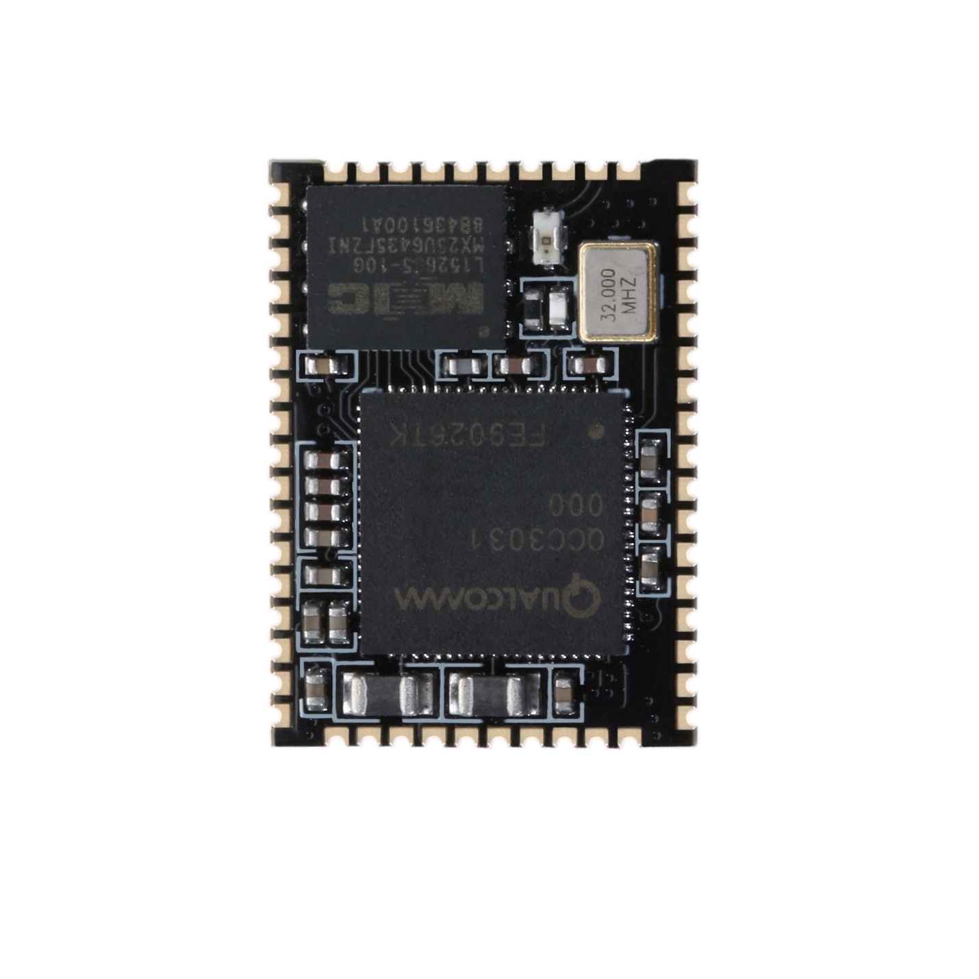
I have this module - BTM331.
I would like to ask you to share your experience, how connect this chip to USB? How configure DSP Kalimba on this chip by USB?
On USB we have 4 pins
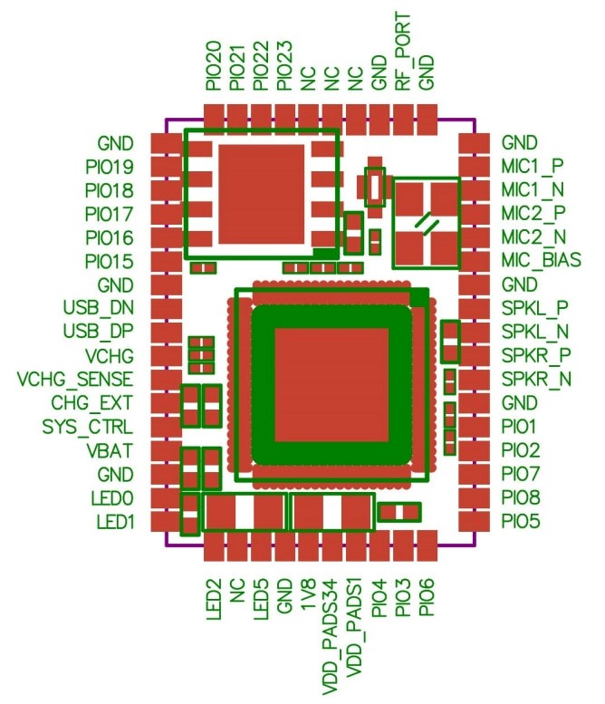
And we have pins on QCC3031(BTM331):
Which pins from qcc3031 I need to connect to USB pins?
As I understood Data+ and Data- from USB need to connect to USB_DN, USB_DP from QCC3031.
I have had quite a lot of experience with portable speaker design and Bluetooth modules from Qualcomm. I worked with CSR chips, for example, CSR64215 and I didn’t get any problem with programming this chip. Moreover, we have a great thread on this forum with a lot of useful information: CSR8675 programming guide w. software and tons of CSR info
On the market, we have new Qualcomm chips QCCXXXX and the approach of programming not the same with CSR modules. As far as I know, the last chip that supports CSR programming process is QCC3008.
And new chips have features:
- APTX-HD, APTX-Adaptive (QCC5125)
- DSP Kalimba, a key feature for me.
- Bluetooth 5.1
- Ready-made modules with amplifiers and external DACs
These chips have DSP Kalimba and that gives the opportunity to set up audio how I want, make limiter, EQ, bass booster, etc.
I know that this DSP not so powerful as, for example, ADAU1701, but that makes my project chipper using only one chip for wireless connection, DAC and DSP.
QCC5125 and QCC3034\QCC3031 have the same programming approach. For programming those modules, we have two ways. First, we need special programming expensive board. Second, programming with USB.
I found ADK for QCC3031 on the thread that I write above, thanks a lot @ErikDIY for that. I tried to connect this chip to a USB, but I didn’t get any success.
I have this module - BTM331.
I would like to ask you to share your experience, how connect this chip to USB? How configure DSP Kalimba on this chip by USB?
On USB we have 4 pins
- GND,
- Data+
- Data-
- +5V
And we have pins on QCC3031(BTM331):
- VBAT_SENSE
- USB_DN
- USB_DP
- VCHG
- VCHG_SENSE
- CHG_EXT
Which pins from qcc3031 I need to connect to USB pins?
As I understood Data+ and Data- from USB need to connect to USB_DN, USB_DP from QCC3031.
Attachments
Last edited:
If you Google the keywords qcc usb_dn usb_dp you'll find the datasheet for qcc5120 and in it there is an example diagram that shows where you need to connect USB_VBUS. That is probably needed to activate the USB subsystem. The datasheet also states that the ADK documentation has the necessary info for programming the chip, maybe it includes the connection info.
If you Google the keywords qcc usb_dn usb_dp you'll find the datasheet for qcc5120 and in it there is an example diagram that shows where you need to connect USB_VBUS. That is probably needed to activate the USB subsystem. The datasheet also states that the ADK documentation has the necessary info for programming the chip, maybe it includes the connection info.
Hi, thanks for your comment.
I opened QCC3031 datasheet and found information about USB:
"The transaction bridge is an external bridge into the internal transaction bus between QCC3031 QFN subsystems. It
is the primary debug interface and can also be used for production programming."
"A direct USB2.0 connection from a host computer to the QCC3031 QFN can be used for most
debugging and programming activities. For more details, see ADK documentation."
"TRBI200 use is not mandatory for flash programming or other manufacturing operations. Those actions
are performable using direct USB connection to the QCC3031 QFN USB device interface."
And in datasheet, I found this "USB_VBUS (VCHG)" - is it mean that + from USB need to connect to VCHG?
GND -> GND
Data+ ->USB_DP
Data- ->USB_DN
+5V ->VCHG
Am I right? Or need something else?
The 5120 datasheet has an example diagram which shows USB_VBUS connected to multiple pins. I don't know if 3031 is different.
I tested connection:
GND -> GND
Data+ ->USB_DP
Data- ->USB_DN
+5V ->VCHG
And it works! I unlocked the device and now I'm trying to work with MDE.
Do anybody has experience work with MDE?
How can I change the Bluetooth name with MDE?
How can I config DSP Kalimba?
Hi,
sadly i´m not able to contribut anything useful now.
Just wanted to state that i´m verry interested in your project sice i´m planing on using this exact chip aswell(my project did not progess to this point jet, and i decided to postpone this mystery). I got my self a qualcom ID in order to find information abaut how to programm these chips. But wasent able to find any useful informatin alltho i look trou all the arrivable Qualcomm platforms.(You need to veryfy as a thrusted company in order to gain accas to the useful stuff(but i guess those are no new insights))
What i guess to know is that one needs BloueSuite in order to programm these chips but im not sure abaut that? Since the coresponding usermanual is useless as well.
I wisch you good stamina//luck to figure these things out.
Hi,
sadly i´m not able to contribut anything useful now.
Just wanted to state that i´m verry interested in your project sice i´m planing on using this exact chip aswell(my project did not progess to this point jet, and i decided to postpone this mystery). I got my self a qualcom ID in order to find information abaut how to programm these chips. But wasent able to find any useful informatin alltho i look trou all the arrivable Qualcomm platforms.(You need to veryfy as a thrusted company in order to gain accas to the useful stuff(but i guess those are no new insights))
What i guess to know is that one needs BloueSuite in order to programm these chips but im not sure abaut that? Since the coresponding usermanual is useless as well.
I wisch you good stamina//luck to figure these things out.
Hi! Thanks for your support)
I have Qualcomm ID and sometimes you can find there very useful information.
You need BlueSuite to unlock the chip and upload dump (DFU) on the chip, at least. I'm sure this is not all functions of BlueSuite)
I found out that we have two options of upload dump on the chip - 1 with BlueSuite by USB and 2 with Android application OTA (On-The-Air).
I understood how to use Kalimba, need QACT_v7.2.8 for that.
I put here useful links:
QCC --- MDE use introduction - Programmer Sought
QCC30DFU Process Android Description, QCC512X QCC302X QCC303X Earbud Software GAIA OTA DFU Air upgrade implementation method and upgrade steps ... - Programmer Sought
Qualcomm QCC30xx_QCC51xx_How to DFU upgrade OTA upgrade - Programmer Sought
I'm sure that on this forum users who have all the necessary experience for programming those chips and if they help me it will be more productive)
By the way, I still don't know how to rename this chip
")
I take my words back, I know how to rename the chip, this is simple, when you create a project in MDE, the name of the project will be the name of the chip after the DFU process.

I understood how to change settings and upload these to the chip. I will check it first on my chip and will let you know.
Based on my experience with CSR chips I can say that QCC30XX chips are more intelligent. MDE gives you quate more opportunities than PSTool.
I understood how to change settings and upload these to the chip. I will check it first on my chip and will let you know.
Based on my experience with CSR chips I can say that QCC30XX chips are more intelligent. MDE gives you quate more opportunities than PSTool.
Attachments
Last edited:
Hi,
sadly i´m not able to contribut anything useful now.
Just wanted to state that i´m verry interested in your project sice i´m planing on using this exact chip aswell(my project did not progess to this point jet, and i decided to postpone this mystery). I got my self a qualcom ID in order to find information abaut how to programm these chips. But wasent able to find any useful informatin alltho i look trou all the arrivable Qualcomm platforms.(You need to veryfy as a thrusted company in order to gain accas to the useful stuff(but i guess those are no new insights))
What i guess to know is that one needs BloueSuite in order to programm these chips but im not sure abaut that? Since the coresponding usermanual is useless as well.
I wisch you good stamina//luck to figure these things out.
I think I have killed my chip, but in the case of these chip, I still can connect to it by USB, but when I trying turn in on I have only one short flashlight and that's it.
Unfortunately, I didn't take a dump before testing (I didn't know how).
May I ask you to make a dump of your chip and share it with me?
NvsApp.exe this app in BlueSuite can create a dump.
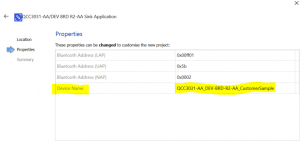
Hi. I am also learning about MDE.
But have you used "QCC_Tool" to change the name and address?
But have you used "QCC_Tool" to change the name and address?
An externally hosted image should be here but it was not working when we last tested it.
Hi. I am also learning about MDE.
But have you used "QCC_Tool" to change the name and address?
I could not find this tool in my installation folders, can you give me the installation path of this tool, or please share with me this .exe tool.
I haven't bought it yet, it needs late registration per computer.
Hi all, I have updates about configuring QCC3034, and let me share those with you guys.
First many thanks to @hvmcsa, he shared with me qcc_tool where I can change the name of the chip.
Second, about backup. I understood how backup original firmware. You need to use NvsApp.exe in BlueSuite. And it works. I backed up the original firmware with this tool, broke my chip after MDE deployment, and successfully restored it from backup. Rule #1 before any changes do backup!
Third, about Kalimba DSP. You can config DSP with the QACT tool. Need to enable chip, connect to it with Bluetooth and USB, and run some audio, that gives you enable online configuration. But I have some problem with that, I can't save config on my chip. After rebooting the chip all settings became the default. And I don't know how to fix that.
How save DSP settings on the chip after reboot?
Could somebody help me with the correct orders and steps to save DSP config?
Thanks.
Last edited:
Hi all, hi German1212,
I‘m new to this forum and I registered because of this thread to be honest.
So my problem is the following:
I have a Wondom Jab4 bluetooth power amp, which is actually using a qualcomm qcc3034.
I know Wondom proposes a service for changing the pairing name, so the pairing name should be changable after production.
There is a 5-pin connector on the backside of the board just under the bt-module called J3, which is not labeled.
I got an answer from Wondom, telling me that I should use the qualcomm programmer, which is extremelly expensive. I also got the answer about the pinout of J3.
as follows:
1 -> MOSI
2 -> MISO
3 -> CLK
4 -> 3V3
5 -> GND
Do I have another possibility to change the „friendly name“ than using the qualcomm programmer?
If yes, would you mind sharing your experiences with me?
thanks in advance!
cheers, F.
Hi all, hi German1212,
I‘m new to this forum and I registered because of this thread to be honest.
So my problem is the following:
I have a Wondom Jab4 bluetooth power amp, which is actually using a qualcomm qcc3034.
I know Wondom proposes a service for changing the pairing name, so the pairing name should be changable after production.
There is a 5-pin connector on the backside of the board just under the bt-module called J3, which is not labeled.
I got an answer from Wondom, telling me that I should use the qualcomm programmer, which is extremelly expensive. I also got the answer about the pinout of J3.
as follows:
1 -> MOSI
2 -> MISO
3 -> CLK
4 -> 3V3
5 -> GND
Do I have another possibility to change the „friendly name“ than using the qualcomm programmer?
If yes, would you mind sharing your experiences with me?
thanks in advance!
cheers, F.
Hi, you can change the name with a tool that @hvmcsa provided to me. It calls QCC tool: QCC_Tool_v1.0.3.zip — Яндекс.Диск.
You need to find the next pins on your Bluetooth chip:
- GND
- USB_DP
- USB_DN
- VCHG
After that you will be able to connect to it by USB:
GND -> GND
Data+ ->USB_DP
Data- ->USB_DN
+5V ->VCHG
By the way, I googled the board "Wondom Jab4" this is quite good stuff, this board has external DSP chip ADAU1701, this is a very powerful chip for good sound quality.

Hi all,
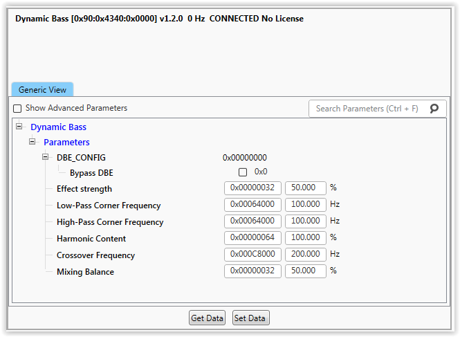
I continue working with QACT and I have questions about the Dynamic Bass feature. As I understood this is clever thing to bass boost better than just a simple equalizer. This is really digital sound science. I found documents but this is difficult to understand, that's why I ask. This is a useful link: https://citeseerx.ist.psu.edu/viewdoc/download?doi=10.1.1.524.4796&rep=rep1&type=pdf
Did anybody work with that feature?
How configure it correctly?
What does mean Harmonic content?
I will be happy your any ideas and experience about it.
Attachments

My guess, by harmonic content, is digital sound processing, that looks at the fundamental bass content of the source material and then adds in additional 2nd and 3rd harmonics to provide the illusion of bass.
Like if your speakers only go down to 100Hz, 50Hz will sound like nothing, especially if you have a high pass to protect the drivers from over excursion in passive radiator/ported cabinets. So lets say the song plays 50Hz and through those speakers it sounds extremely bass light. The DSP adds in additional harmonics at 100Hz and 150Hz and provides the illusion of some bass being present.
Question German, the ADK that you linked to comes with an ADK configuration tool. Does this work via USB programming for you? It should allow you to change a variety of settings to suit your intended application without having to rewrite source code. I am trying to figure out if this only works via the SPI programmer or if it is also possible via USB. Thanks.
My guess, by harmonic content, is digital sound processing, that looks at the fundamental bass content of the source material and then adds in additional 2nd and 3rd harmonics to provide the illusion of bass.
Like if your speakers only go down to 100Hz, 50Hz will sound like nothing, especially if you have a high pass to protect the drivers from over excursion in passive radiator/ported cabinets. So lets say the song plays 50Hz and through those speakers it sounds extremely bass light. The DSP adds in additional harmonics at 100Hz and 150Hz and provides the illusion of some bass being present.
Question German, the ADK that you linked to comes with an ADK configuration tool. Does this work via USB programming for you? It should allow you to change a variety of settings to suit your intended application without having to rewrite source code. I am trying to figure out if this only works via the SPI programmer or if it is also possible via USB. Thanks.
Hi,
Answer to your question - Yes, ADK works perfectly with USB. I have configured at least 3 modules 3031\3034 via USB.
Thanks for your answer. I figure out how it works, but I'm not sure what parameters a need to set for the best sound.
For example, I have a speaker with passive radiators and speakers 2.0 with fs 103 Hz. What are the parameters I should set?
Effect strength - 50%
Low-Pass Corner Frequency - 150 Hz
High-Pass Corner Frequency - 50 Hz
Harmonic Content - 50% (How does this parameter affect the sound?)
Crossover Frequency - 150 Hz
Mixing Balance - 40%
Are those parameters good for this speaker?
Thanks.
I really do not know how the parameters affect the bass enhancement as it sort of implies that there could perhaps be a separate low frequency channel too somewhere. Maybe this is possible as I know an LFE/sub output is part of the configuration somewhere, but who knows.
I'm assuming that harmonic content would determine how many additional harmonics are generated. Some % might = 2nd harmonic only, a higher % might mean 2nd and 3rd are generated etc.
Effect strength vs mixing balance is confusing as I could see both of them doing exactly the same thing. In other words how much of these additional harmonics are added to the original sound.
The high-pass corner implies the -3dB point for a high pass that would ordinarily protect the speaker from frequencies it cannot produce. Obviously we've no idea what the slope type used is.
The low-pass corner could be asking how high up in frequency do you want the additional harmonics to be added, or it could be how high up do you want the enhancement to detect the presence of the bass fundamental.
The crossover frequency is kind of bizarre as a parameter for this.
Without an explanation as to what the settings do you're just going to have to give it a go and see.
If you wanted to quantify the results you could connect the output of the bluetooth module to the input of a soundcard. Play sine tones and white noise as stimuli on a phone with an appropriate app and then alter the parameters of the enhancement and see what happens.
- Home
- Source & Line
- Digital Line Level
- QCC5125 and QCC3034\QCC3031 programming