I really do not know how the parameters affect the bass enhancement as it sort of implies that there could perhaps be a separate low frequency channel too somewhere. Maybe this is possible as I know an LFE/sub output is part of the configuration somewhere, but who knows.
I'm assuming that harmonic content would determine how many additional harmonics are generated. Some % might = 2nd harmonic only, a higher % might mean 2nd and 3rd are generated etc.
Effect strength vs mixing balance is confusing as I could see both of them doing exactly the same thing. In other words how much of these additional harmonics are added to the original sound.
The high-pass corner implies the -3dB point for a high pass that would ordinarily protect the speaker from frequencies it cannot produce. Obviously we've no idea what the slope type used is.
The low-pass corner could be asking how high up in frequency do you want the additional harmonics to be added, or it could be how high up do you want the enhancement to detect the presence of the bass fundamental.
The crossover frequency is kind of bizarre as a parameter for this.
Without an explanation as to what the settings do you're just going to have to give it a go and see.
If you wanted to quantify the results you could connect the output of the bluetooth module to the input of a soundcard. Play sine tones and white noise as stimuli on a phone with an appropriate app and then alter the parameters of the enhancement and see what happens.
Thanks a lot for that clarification.
I would like to add my experience about three options:
Effect strength - this is a percent of increasing bass
Mixing balance - this setting defined proportion between bass and hight\midle sound.
The crossover frequency - defines what exactly is a bass and what is a hight\midle. This is need for Mixing balance percent. In other words, if you set crossover frequency 150Hz and Mixing Balance 40%, the frequencies before 150Hz will play only on 40 percent, and frequencies after 150Hz will play on 60%.
Just in case, I'm not an expert on this, this is only my experience of configuring bass enhancing.
Thanks.

Hi German1212, would you be willing to share a QCC3031 dump so that I can play around with ADK while I wait for the modules to arrive?
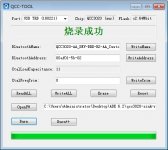
Hi all, I have updates about configuring QCC3034, and let me share those with you guys.
First many thanks to @hvmcsa, he shared with me qcc_tool where I can change the name of the chip.
Second, about backup. I understood how backup original firmware. You need to use NvsApp.exe in BlueSuite. And it works. I backed up the original firmware with this tool, broke my chip after MDE deployment, and successfully restored it from backup. Rule #1 before any changes do backup!
Third, about Kalimba DSP. You can config DSP with the QACT tool. Need to enable chip, connect to it with Bluetooth and USB, and run some audio, that gives you enable online configuration. But I have some problem with that, I can't save config on my chip. After rebooting the chip all settings became the default. And I don't know how to fix that.
How save DSP settings on the chip after reboot?
Could somebody help me with the correct orders and steps to save DSP config?
Thanks.
Any advice on using QCC_Tool? It's in Chinese and I'm struggling to make sense of it even with translators
Hi German1212, would you be willing to share a QCC3031 dump so that I can play around with ADK while I wait for the modules to arrive?
Hi, I have only the dump in .xuv extension.
This is the link on it - Dump_QCC3031_Original.xuv — Яндекс.Диск
But I'm not sure that dump can help you.
Any advice on using QCC_Tool? It's in Chinese and I'm struggling to make sense of it even with translators
My advice will depend on your goals of using this app. It works for me.
I hope this picture will help you.
Attachments
It does, thank you. It's weird that mine is in Chinese, I used the link you provided earlier in the thread
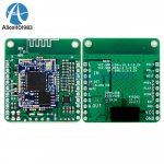
I got one of these QCC3031 boards. Does anyone know which are the USB pins?
There's smaller solder holes on the left side labelled N, B, P, V, G. Just a random guess but could it be this?
N - USB_DN
P - USB_DP
V - VCHG
G - GND
I'm wondering if anyone has programmed this specific design before. I really don't want try a random guess and blow up my board.
There's smaller solder holes on the left side labelled N, B, P, V, G. Just a random guess but could it be this?
N - USB_DN
P - USB_DP
V - VCHG
G - GND
I'm wondering if anyone has programmed this specific design before. I really don't want try a random guess and blow up my board.
Attachments
I got one of these QCC3031 boards. Does anyone know which are the USB pins?
There's smaller solder holes on the left side labelled N, B, P, V, G. Just a random guess but could it be this?
N - USB_DN
P - USB_DP
V - VCHG
G - GND
I'm wondering if anyone has programmed this specific design before. I really don't want try a random guess and blow up my board.
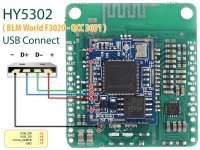
About labeled holes on the board, in my case this is not working for me, I connected directly to the pin on the chip, the pictures on the first page can help you with that.
GND -> GND
Data+ ->USB_DP
Data- ->USB_DN
+5V ->VCHG
If you have a multimeter you can check contacts on the chip and on the lebeled hols.
I don't think the one I have is the BTM331. The board design looks different. The pin layout is different.
I haven't been able to find any schematics for it other than basic diagrams on seller pages.
I haven't been able to find any schematics for it other than basic diagrams on seller pages.
From the picture you sent 1.27mm pitch pins are top to bottom
1 - NC
2 - D-
3 - NC
4 - VBAT
5 - D+
6 - VCC
7 - GND
I have the same board and I don't remember where I found it but I found a datasheet for the BTM331 and was able to trace out the pinout to confirm them. To be clear your connections between the two will be
USB QCC30XX
VCC 1 --> 6
D- 2 --> 2
D+ 3 --> 5
GND 4 --> 7
I have the same board and I don't remember where I found it but I found a datasheet for the BTM331 and was able to trace out the pinout to confirm them. To be clear your connections between the two will be
Thank you. It works.
Unfortunately my board broke a few days ago. In the middle of listen to audio, it randomly died. When power is connected, one LED turns on for a second then goes out.
I wired up a USB cable and it is detected by the computer. I installed the drive and applied the unlock steps. It showed up in the NVS app. I was able to dump the firmware. The verify command and it was very flakey, failing to verify more often than not.
I tried to erase and reflash. But after erasing it is no longer detected by the NVS app. The USB devices still show up in Device Manager but nothing else works. So I guess it's really borked now. I noticed the firmware dump from my board is 28MB vs 57MB that German1212 posted earlier.
I got my module, and I'm trying to unlock the USB programming mode.
German1212 or anyone else, do you have the installer for Bluesuite 3.1.4 or higher? I can't seem to register on 52Bluetooth.
German1212 or anyone else, do you have the installer for Bluesuite 3.1.4 or higher? I can't seem to register on 52Bluetooth.
I got my module, and I'm trying to unlock the USB programming mode.
German1212 or anyone else, do you have the installer for Bluesuite 3.1.4 or higher? I can't seem to register on 52Bluetooth.
See reply 70 and 177 in the CSR675 thread.
https://www.diyaudio.com/forums/dig...ide-software-tons-csr-info-7.html#post6534524
https://www.diyaudio.com/forums/dig...de-software-tons-csr-info-18.html#post6772891
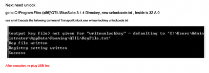
Thanks. I was able to get Bluesuite from the dropbox folder.
I'm following the steps in the PDF and have created a file with 32 A 0 but TransportUnlock.exe is complaining:
Code:
==============================================================================
ERROR: Key of invalid length at line 1 of key file 'unlockcode.txt'
==============================================================================
Failed
Any thoughts?
Attachments
Thanks. I was able to get Bluesuite from the dropbox folder.
I'm following the steps in the PDF and have created a file with 32 A 0 but TransportUnlock.exe is complaining:
It means 32 zeros. Like this:
Code:
00000000000000000000000000000000
Hi i am new to this stuff. i am trying to build a diy headset wit the QCC5125 SOC from Aliexpress.
I have connected a PCM5102A to the I2S bus just to be sure i didn`t break it on the first try. It plays sound so i got a wireless headphone now. So my question is do i need to enable something in the adk configuration tool to set it to enable the dual microphone function? I stil need to get the components for the dual microphone circuit ( nothing connected at the moment ).
I have connected a PCM5102A to the I2S bus just to be sure i didn`t break it on the first try. It plays sound so i got a wireless headphone now. So my question is do i need to enable something in the adk configuration tool to set it to enable the dual microphone function? I stil need to get the components for the dual microphone circuit ( nothing connected at the moment ).
It seems unclear which boards are actually programmable at all. And which tools work with those that are programmable.
From what I can gather from other comments around the web, some variants have limited programmability. There's one post on 52bluetooth where the OP could not use any of the tools with their qcc3031. At least that's what it seems like from the translation.
The board I posted earlier burned out before I tried the USB connection so I don't know if it's not programmable because part of the chip blew up. These boards are too expensive to try random boards to find out which one can be programmed. Especially since they appear to break so easily.
- Home
- Source & Line
- Digital Line Level
- QCC5125 and QCC3034\QCC3031 programming