I have no idea why ANYONE would want to Zero the SDM pulse train on Mute - this will ONLY cause Thumps and clicks as the music is Muted and Unmuted...
The correct action on "No Change of Audio input Data after a period" depends on the modulator design - some have a small added DC offset - so you just want the modulator left to do its thing with "Zero" input Data.
Some SDM modulators produce either a 50:50 pattern for "silence" or a variation of this 50:50 pattern to reduce the EMI output (spread spectrum) – IIRC a reduced EMI “Mute” pattern is specified in the DSD spec.
But the VERY last thing you want is a modulator to “Zero” (Outputs go Low or High) on “Mute” - this will result in all manor of unavoidable Thumps and clicks on audio restart...
Agree with John. A mute signal is probably best used to mute the analog output of a dac, not the DSD modulator output stream.
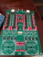
I'm attached 2 led bulbs: one for Mute leg (pin-11) and one for DSD_En leg (pin-7).
I am sure they work correctly.
When I click the stop/pausing on HQ Player the Mute-led are led-on, and change to led-off while playing.
DSD_On-led are led-on if DSD playing and led-off when PCM playing.
You should use the CPLD_1081 + firmware_2006be11 and try again.
I think thjat is what is supposed to happen.
I have no idea why ANYONE would want to Zero the SDM pulse train on Mute - this will ONLY cause Thumps and clicks as the music is Muted and Unmuted...
The correct action on "No Change of Audio input Data after a period" depends on the modulator design - some have a small added DC offset - so you just want the modulator left to do its thing with "Zero" input Data.
Some SDM modulators produce either a 50:50 pattern for "silence" or a variation of this 50:50 pattern to reduce the EMI output (spread spectrum) – IIRC a reduced EMI “Mute” pattern is specified in the DSD spec.
But the VERY last thing you want is a modulator to “Zero” (Outputs go Low or High) on “Mute” - this will result in all manor of unavoidable Thumps and clicks on audio restart...
Never had a problem regarding thumping/clicking.
surely can be a problem, but if the mute handles correctly the output you only hear music.
but YMMV.
Last edited:
I have no idea why ANYONE would want to Zero the SDM pulse train on Mute - this will ONLY cause Thumps and clicks as the music is Muted and Unmuted...
Some peculiarity of the FIFO board, see posts 72, 74 and 78.
Pjotr, can you tell me if the FPGA handles the "DSD_ON" signal at the output ?
i can rely on it or is passed trought like the mute ?
DSDon is supported by fpga. But practically it is always "1" 🙂
Because we always have DSD in the output 🙂
If we use PCM at the input, we have DSD at the output and DSDon "1".
If we use DSD at the input, passed thru mode is activated and we have original DSD at the output and DSDon "1".
Never had a problem regarding thumping/clicking.
surely can be a problem, but if the mute handles correctly the output you only hear music.
but YMMV.
To reproduce an integrated symmetrical audio output from an SDM stream (reproducing an Audio signal that can swing though Positive, Ground, Negative and back again), "1" is Positive, "0" is Negative and Ground is 50:50 (Obviously after integration).
So if you want a Ground referenced signal the modulator needs to be producing a 50:50 signal (or one that integrates to a mid level voltage) – this mid level voltage in effect becomes the audio signals 0V (or one that integrates to a mid level voltage in the case of the EMI reducing Spread Spectrum pattern).
So if you "Mute" the SDM output to continuous L or continuous H you are in fact swinging the audio output to max positive or max Negative DC signal level – so you would have full level DC on your audio outputs if it where not for AC coupling capacitors or a transformer – its also not good to put DC into a transformer...
After “Unmuting” from continuous L or continuous H state – the audio output has to go from full negative or full positive to a mid level to swing about “Audio Ground Level”... this will result in a thump or click as the DC levels are restored...
This is TOTALLY incorrect operation, and asking for something that is operating correctly (50:50 modulation during digital silence), to be incorrect (continuous L or continuous H ) is simply not done...
You dont bodge the modulator to fix bad design somewhere else...
Some peculiarity of the FIFO board, see posts 72, 74 and 78.
Hi Marcel,
I think the OP is sligltly confused, I'm GUESSING the FiFo needs to be flagged Audio Mute condition to Reset the FiFo memory to prevent eventual memory under / overflow - but surely just a Mute signal line to the FiFo wil do - no need for the modulator to have anythig to do with it?
How would the FiFo deal with a true DSD signal that behaves EXACTLY as the moduators SDM output - the DSD stream does not goto continuous L or continuous H during digital silence - its does excatly as the SDM modualtor does - longterm 50:50...
I see you have also commented on the requirement for 50:50 in your ealier points excatly due to DC conditions (preventing thumps and clicks)...
The OP needs to look into a discrete Mute (Reset) line to the FiFo - NOT relying on "Zero" input otherwise it will never work as intended with an SDM or Native DSD stream...
I don't think i'm confused... 🙂
I don't want to rewrite the rules of sigma-delta conversion. and i agree on every point you and others made about it !
a free running SDM is indeed in the rights of outputting 50% "1"s and 50% "0"s.
BUT
i have solution made from "others" (McFifo, Pure network endpoing, DSC) that have proven to be good enough even when output is slammed to full HIGH or LOW state.
muting on the DSC works by shorts the primary side of the xfrms, and no current flow trought it, just trought the switch itself that closes the contact.
McFifo at the moment (and i have asked Ian for more information about it) detects end of stream by looking at the data in the buffer.
I am trying to make everything works together.
If i had the mean to make it the whole contraption myself, i wasn't here discussing on how to "bodge" things 🙂
In any case, i am sure i have found a potential solution gating the outputs, and i will post the results once i have the assembled gadget in my hands.
thanks 🙂
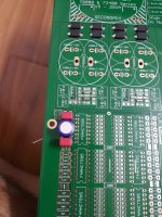
Pjotr, can i know the distance between the mouting holes and the x-y distance from the nearest 2x10 input/output connectors ? thanks
Pjotr, can i know the distance between the mouting holes and the x-y distance from the nearest 2x10 input/output connectors ? thanks
This is the Amanero format:
https://amanero.com/drivers/combo384-D.pdf
Hello, please post the electrical circuit. I want your project to insert into my fee with my source. This will reduce the time to extract the scheme from gerbers files. Thank youIt's nice to present this project - separate delta sigma modulator for a dsc2 dac.
Special thanks to Jussi and Pavel.
The basic idea is to convert pcm to a dsd stream without the use of a PC.
Design flow goes as follows:
i2s serial data is converted to parallel, next we have the first interpolation fir filter,
in this filter the data is oversampled x2, x4 or x8 - this depends on the incoming data rate.
(for 44.1kHz we have x8 interpolation, for 96kHz x4 and for 192kHz x2)
next, the data is going to the two stage CIC filter and is oversampled x32 to final x256
Then the data is going into the sigma delta 7 order modulator, which has classical CRFB structure,
as I said earlier all arithmetics are done in CSD arith, so no multipliers here.
all coefficients are carefully optimized using delsig package
If someone asks, yes, there are g0, g1, g2 coeffs.
At the end the dsd streams are time aligned using ODDR2 primitives
XC6SLX9 is almost full, so there is no ability to add anything 🙂
To upload the attached bitstream file to the board you need a Xilinx programmer cable and Xilinx program Impact.
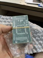
In the next post my friend PJotr will post gerber files, BOM and some measurements.
I hope this project will be interesting for someone.
DIY use only!

Your schematic suggests 0.1second(mute-on period) continuous zero of DSD1, DSD2, and DSD_CLK can assert a mute signal on your FIFO. Amanero will assert their mute signal 4milisec prior to Amanero-5pin(DATA), post#91 timing diagram. I guess 4milisec continuous PCM not-zero is the trigger of Amanero 's mute signal. I think the same function can be implemented into FPGA because unused block memory is still enough to do the job. If it works well, you don't need an additional PCB.🙂
Last edited:
That seems to contradict post #79, unless you suggest to redesign the board.
Edit: this remark is incorrect, because xx3stksm's idea of post #114 wouldn't require the Amanero's mute signal.
Edit: this remark is incorrect, because xx3stksm's idea of post #114 wouldn't require the Amanero's mute signal.
Last edited:
Yes, mute from Amanero isn't connected to FPGA. If continuous not-zero of Amanero-5pin(DATA) is the trigger of Amanero's mute(11pin), it's OK to do the same job without Amanero's mute. But I have found the situation is a bit complicated. Foobar doesn't assert Amanero's mute when it's in "pause" state while "play" does. Windows media player is far complicated. It assets Amanero's mute only once, the first playback only. So, Amanero's mute is under the control of software. Amanero-5pin(DATA) probably can't be the alternative to Amanero's mute(11pin).
@chientechnical,
AK4137 is like a dac in that the implementation around it has a lot to with the best sound quality it can produce. That may mainly have to do with its internal PLL, which can be used in different ways depending on how the chip is configured. PLLs like that tend to get disturbed by noisy power rails. Cleaning up the power and the implementation in general can make AK4137 perform better than any of the Chinese AK4137 boards do.
Similarly, with an FPGA DSD converter, one might expect that things like isolation, reclocking, etc., might help clean up the signals and noise that come into the dac.
If one doesn't account for those sorts of things, then listening comparison results wouldn't necessarily mean much.
Tks u. I'm refreshing the 4x DSC parallel different balance (or 8x).
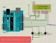
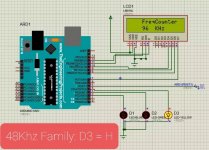
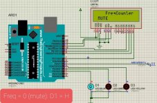
I used LT3045 regulator for all DSC, Amanero, and isolator too. Crytek clock clean are on DAC side with support of Arduino count frequently for switch select 44.1/48Khz family and mute function, and isolated too.
How the Arduino can detect the PCM or DSD being transmitted. Sorry I'm my-learn from the Internet and have a bit of a hobby for self-made audio.
Attachments
Last edited:
- Home
- Source & Line
- Digital Line Level
- Simple DSD modulator for DSC2