Thank you! I also found a datasheet here:
https://osch.oss-cn-shanghai.aliyuncs.com/blogAttachment/1553654893094.pdf
And I read this:
The SPI_PCM# line needs to be pulled high externally to use the SPI interface.
Unfortunately I cannot really understand what this means.
https://osch.oss-cn-shanghai.aliyuncs.com/blogAttachment/1553654893094.pdf
And I read this:
The SPI_PCM# line needs to be pulled high externally to use the SPI interface.
Unfortunately I cannot really understand what this means.
Thank you! I also found a datasheet here:
https://osch.oss-cn-shanghai.aliyuncs.com/blogAttachment/1553654893094.pdf
And I read this:
The SPI_PCM# line needs to be pulled high externally to use the SPI interface.
Unfortunately I cannot really understand what this means.
That means you need to "pull" the potential of that pin on the High Level.
On page 18 of the datasheet of the QCC3008 you see the following:

That means, the pin has a pull down resistor, which will pull the potential of this pin to ground (0V) if there is no external voltage applied. From a digital logic perspective, that translates to the state "0", which - as described in the datasheet - means that the SPI interface will work in I²S/PIO mode.
If you want this to switch to "1" aka. SPI mode, you will have to apply a voltage to that pin that is the same as on the pin "VDD_PADS_1".
From their example schematic it seems that usually that would be the 1.8V supply line.

So to get the SPI mode enabled, you should try to tie the pin SPIPCM to 1.8V.
It should make no difference if you are using the 1.8V from the module or from the programmer.
From your images it looks like you are using those pins on the edge of the breakout board. What prevents you from using the ones on the two pinheaders on the side? E.g. connecing CSB, MOSI, MISO and CLK directly there instead on those tiny pins on the side (which are labeled weirdly).
From your images it looks like you are using those pins on the edge of the breakout board. What prevents you from using the ones on the two pinheaders on the side? E.g. connecing CSB, MOSI, MISO and CLK directly there instead on those tiny pins on the side (which are labeled weirdly).
Yes I'm using that smallest, but I already made a check, there is continuity and correspondence between these and the ones directly on the side of the module. I mean CSB MOSI CLK and MISO (the letter on the smallest should be the last letter of the connection e.g. MISO = o MOSI = i).
Alright, I guess then we can rule that issue out. Pretty strange. The message you get from PSTool, does it have a message in brackets as well e.g. "Unable to detect chip type (XXX)" or is it just the plain message?
Could be, not sure about that, that they've locked the QCC3008 on your module. Hard to rule that out though. Haven't worked with those chips a lot
Could be, not sure about that, that they've locked the QCC3008 on your module. Hard to rule that out though. Haven't worked with those chips a lot
Wouldn't try that. As far as I've seen the usual voltage used for that Pin is 1.8V - using 3.3V might fry your QCC3008 :/
Is your module using AptX and is that working? If yes, that could be a reason they locked it. The AptX coded requires a licence key, and perhaps they don't want it to be read out by others.
Is your module using AptX and is that working? If yes, that could be a reason they locked it. The AptX coded requires a licence key, and perhaps they don't want it to be read out by others.
I've used the QCC3031, but never with SPI control. When CSR got bought up/merged (whatever) with Qualcomm, they changed some of the work flow etc. The QCC3008 is the last (that I know of) that uses the "old" SPI programmer. The newer QCC30xx, QCC51xx etc does not use the standard 20$ SPI burner, but the "TRI-burner". This is a +100$ gear that does more or less the same as the cheaper SPI burner. Unfortantly the older SPI burner is not compatible with the TRI-burner (at least from what I know).
Good news tho, is that the QCC3031 can be programmed over USB! You need to connect the DP, DN pins, as well as the charge and sense (?) pin to trigger the QCC3031 into USB mode. When this is done, you need to unlock it. I have a .PDF in my QCC3031 folder HERE on how to unlock USB. The file is called "QCC30xx USB debugging setup".
When this is done, you should be able to change all the params and EQ, although the EQ tool (QACT) is somewhat buggy, and not all firmwares doe have the EQ option enabeled.
Hi, could you please share with me how do you connect USB to QCC3031?
On USB we have 4 pins - GND, Data+, Data-,+5V.
And we have pins on QCC3031(BTM331) - VBAT_SENSE, USB_DN, USB_DP, VCHG, VCHG_SENSE, CHG_EXT.
Which pins from qcc3031 I need to connect to USB pins?
As I understood Data+ and Data- from USB need to connect to USB_DN, USB_DP from QCC3031.
And what about GND and +5V? Which pins need to connect from qcc3031?
Try to connect GND to GND and leave the 5V, since I haven't seen that the BTM331 has any VDD_USB pin, see http://www.tianjiarun.com/zb_users/upload/2020/04/SJR-BTM331_SPEC.pdf
So get the module powered with an external power e.g. 3.3V and only connect DP, DN and GND.
So get the module powered with an external power e.g. 3.3V and only connect DP, DN and GND.
Try to connect GND to GND and leave the 5V, since I haven't seen that the BTM331 has any VDD_USB pin, see http://www.tianjiarun.com/zb_users/upload/2020/04/SJR-BTM331_SPEC.pdf
So get the module powered with an external power e.g. 3.3V and only connect DP, DN and GND.
Thanks for the comment, I will try to test that and let you know.
Try to connect GND to GND and leave the 5V, since I haven't seen that the BTM331 has any VDD_USB pin, see http://www.tianjiarun.com/zb_users/upload/2020/04/SJR-BTM331_SPEC.pdf
So get the module powered with an external power e.g. 3.3V and only connect DP, DN and GND.
I tested that, and it doesn't work.
I soldered directly to D- and D+ on the chip and used VCC and GND. When I connected to my laptop the chip was enabled, but I didn't have any new devices.
Did somebody have the experience configuring QCC3031 by USB? How did you do that?
Any information will useful for me, thanks.
Good
My board has arrived, but out of the blue my CSR programmer has died. Like completely random. I can't really tell what happened. Haven't used it for 1 day, then it stopped working.
Ordered 2 new ones from France, will take some time for them to get here
Also, I got me 2 FTDI FT232RL breakout boards (with hopefully genuine chips on them), which will arrive on Tuesday.
Together with the following project:
GitHub - lorf/csr-spi-ftdi: USB SPI programmer/debugger for CSR BlueCore bluetooth chips, based on FTDI USB to UART converter, for Linux and Windows
I will see if those actually work with my CSR8675 chips and the QC3008 module.
So a bit patience is now needed, yikes
Hi Philipp,
Looking forward to your experiment. I also purchased a Chinese board PA213 with BTM875-B (CSR8675). It is the LDAC version with I2S output. The module is working quite OK but I want to do some simple things with it, like changing the name and reassigning the LEDs.
Currently I only have FTDI boards for programming, but I was not able to connect event to PSTool. I suspect two things: the SPI debugging was locked by the manufacturer or my FTDI chips are fakes. I ordered some genuine ones form TME, but they will arrive in a week or so.
FTDI Programmer: Halfway successful
Hey there, and hey selfy
My FT232RL board arrived yesterday and since I am still waiting on my CSR ISP programmer replacements, I thought to give it a try.
So what did I do?
I tested this on Windows 10 x64, using the following FTDI adaptor:
DSD TECH USB zu TTL Seriell Adapter Konverter mit FTDI: Amazon.de: Computer & Zubehor
This appears to be a genuine one, so I am happy with that.
Then I followed the instructions on here:
GitHub - lorf/csr-spi-ftdi: USB SPI programmer/debugger for CSR BlueCore bluetooth chips, based on FTDI USB to UART converter, for Linux and Windows
And replaced my usbspi.dll in all directories of my ADK 4.3.15 where it occured with the file from the driver package here:
Release 0.5.3 * lorf/csr-spi-ftdi * GitHub
I had to solder additional pinheaders to the FT232RL board, since the pins I needed where not exposed via pinheaders (though they are already prepared).
I did all that and then connected my BTM-875 the following way:
BTM875 => FT232RL
CS# => DTR#
CLK => RTS#
MOSI => RI#
MISO => DSR#
I did not connect any of the LED inputs etc, since I don't need them.
And what can I say? It seems to work for most part:
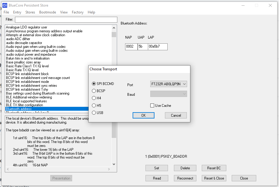
PSTool: yes
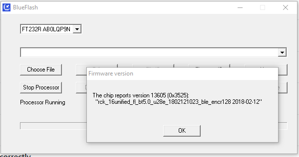
Blueflash: yes
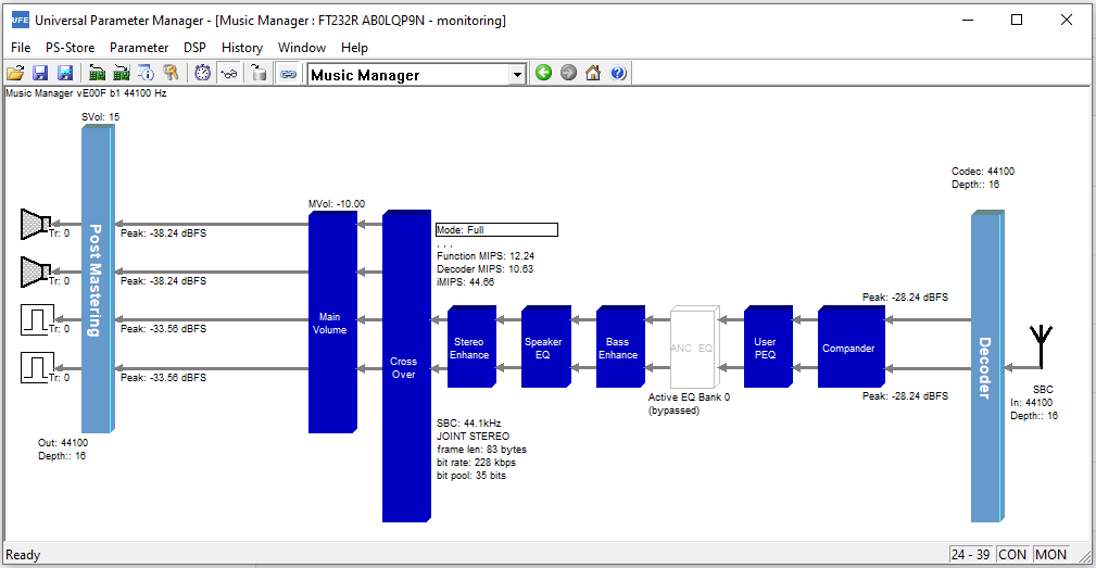
UniversalFrontend: yes
ADK Configuration Tool: no
xIDE: not tested yet
I am not sure why ADK Config Tool is not working, since the other ones are picking the programmer up just fine. Further testing required.
Be aware: Make a backup of the original usbspi.dll files, you will need to switch back to them, if you want to use the original CSR SPI programmer again.
Here are some screenshots from my proof of concept:
Blueflash
PSTool
UniversalFrontend
Hey there, and hey selfy
My FT232RL board arrived yesterday and since I am still waiting on my CSR ISP programmer replacements, I thought to give it a try.
So what did I do?
I tested this on Windows 10 x64, using the following FTDI adaptor:
DSD TECH USB zu TTL Seriell Adapter Konverter mit FTDI: Amazon.de: Computer & Zubehor
This appears to be a genuine one, so I am happy with that.
Then I followed the instructions on here:
GitHub - lorf/csr-spi-ftdi: USB SPI programmer/debugger for CSR BlueCore bluetooth chips, based on FTDI USB to UART converter, for Linux and Windows
And replaced my usbspi.dll in all directories of my ADK 4.3.15 where it occured with the file from the driver package here:
Release 0.5.3 * lorf/csr-spi-ftdi * GitHub
I had to solder additional pinheaders to the FT232RL board, since the pins I needed where not exposed via pinheaders (though they are already prepared).
I did all that and then connected my BTM-875 the following way:
BTM875 => FT232RL
CS# => DTR#
CLK => RTS#
MOSI => RI#
MISO => DSR#
I did not connect any of the LED inputs etc, since I don't need them.
And what can I say? It seems to work for most part:
PSTool: yes
Blueflash: yes
UniversalFrontend: yes
ADK Configuration Tool: no
xIDE: not tested yet
I am not sure why ADK Config Tool is not working, since the other ones are picking the programmer up just fine. Further testing required.
Be aware: Make a backup of the original usbspi.dll files, you will need to switch back to them, if you want to use the original CSR SPI programmer again.
Here are some screenshots from my proof of concept:
Blueflash

PSTool

UniversalFrontend

Thank you very much for the detailed explanation. I will report back as soon as I get my hands on the genuine FTDIs. The only thing which I am doing different is that I am using standalone installation of PSTool (CSR BlueSuite 2.6.6) and not using the whole SDK installation.
Also, I'd like to thank the OP for the huge amount of resources he provided us with!
Also, I'd like to thank the OP for the huge amount of resources he provided us with!
- Home
- Source & Line
- Digital Line Level
- CSR8675 programming guide w. software and tons of CSR info