Thank you very much for the detailed explanation. I will report back as soon as I get my hands on the genuine FTDIs. The only thing which I am doing different is that I am using standalone installation of PSTool (CSR BlueSuite 2.6.6) and not using the whole SDK installation.
Also, I'd like to thank the OP for the huge amount of resources he provided us with!
Perhaps it would be worth a try to check with ADK 4.3.15 - that one gave the best results to me.
Also, one update on the xIDE front:
It appears, after replacing a second UsbIsp.dll that the FTDI SPI is at least showing in the Transport list of xIDE.


Unfortunately, it does not work - neither debugging or transporting over to the CSR8675.

QC3008 hands on: Success!
Good day everybody, hi SGr33n,
I have finally received my CRS ISP programmer replacement and was directory going to try the QC3008 board, that you got.
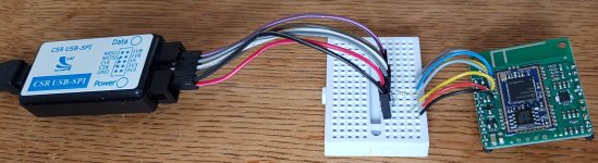
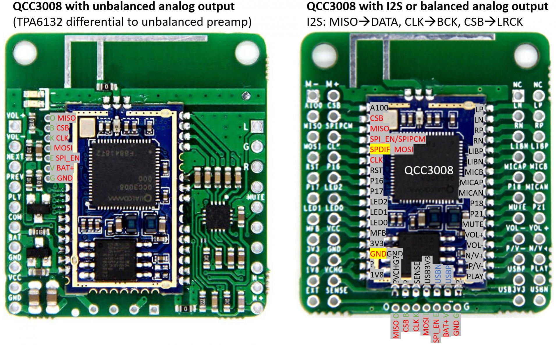
So my connection is the following:
QC3008 Board => CSR SPI
CSB => CSB
CLK => CLK
MISO => MISO
MOSI => MOSI
GND => GND
3V3 => 3V3
SPIPCM => 1V8
You can see some of the connections on the following images.
Please note: It may be necessary to connect VS to 1V8 on the CSR SPI, not 3V3!


I tried the following applications from ADK 4.3.15 (I guess using a more modern ADK would be better, as you see later).
PSTool: works

ADK Config: works

Blueflash: Does not work (no flash detected)

UniversalFrontend: Does not work (probably newer version required)
Good 🙂 so please keep me updated
Good day everybody, hi SGr33n,
I have finally received my CRS ISP programmer replacement and was directory going to try the QC3008 board, that you got.
So my connection is the following:
QC3008 Board => CSR SPI
CSB => CSB
CLK => CLK
MISO => MISO
MOSI => MOSI
GND => GND
3V3 => 3V3
SPIPCM => 1V8
You can see some of the connections on the following images.
Please note: It may be necessary to connect VS to 1V8 on the CSR SPI, not 3V3!


I tried the following applications from ADK 4.3.15 (I guess using a more modern ADK would be better, as you see later).
PSTool: works

ADK Config: works

Blueflash: Does not work (no flash detected)

UniversalFrontend: Does not work (probably newer version required)

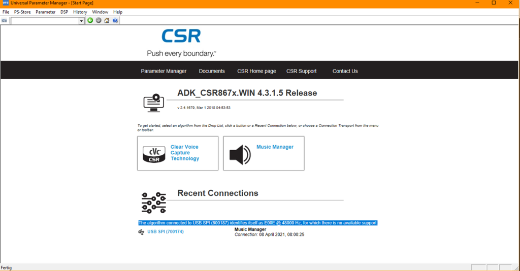
Update:
With the ADK for QC300X from here:
Dropbox - ADK_QCC300x.WIN.1.0.167.exe - Simplify your life
It is working now in UFE:

With the ADK for QC300X from here:
Dropbox - ADK_QCC300x.WIN.1.0.167.exe - Simplify your life
It is working now in UFE:

QCC3008 configuring gone wrong?
Dear folks,
trying to connect QCC3008 (=slave) via I2S to a DSP (=master), I somehow did something wrong to the QCC.
Before changing to I2S, it did work nicely (receiving and sending audio analog in/out - bluetooth). Also connecting to all of the softwaretools worked quite fine.
Here comes the problem (me?): in ADK configuration tool, I tried to enable the QCC I2S interface as slave output and wrote this via the CSR USB-SPI to the board.After that,
SPI_en low/high no difference.
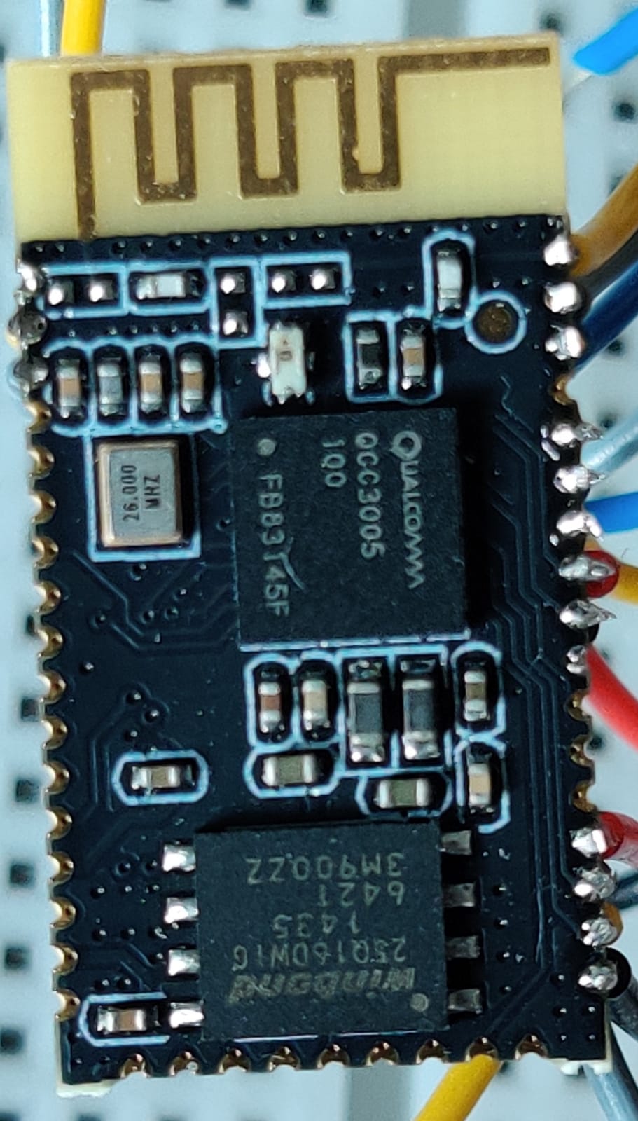
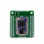
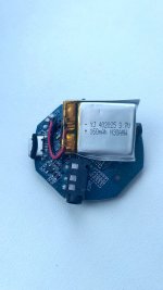
The adapter board itself is a HY5300 (see jpg), pretty similar to the one, TeHSiggi is using

Now my questions to you all:
Best, Josef
Dear folks,
trying to connect QCC3008 (=slave) via I2S to a DSP (=master), I somehow did something wrong to the QCC.
Before changing to I2S, it did work nicely (receiving and sending audio analog in/out - bluetooth). Also connecting to all of the softwaretools worked quite fine.
Here comes the problem (me?): in ADK configuration tool, I tried to enable the QCC I2S interface as slave output and wrote this via the CSR USB-SPI to the board.After that,
- connecting the board via bluetooth is not longer possible
- both LED are permanently on
- no connection to ADK conf. tool (timeout error comes up)
- PStool is still working
SPI_en low/high no difference.
The adapter board itself is a HY5300 (see jpg), pretty similar to the one, TeHSiggi is using

Now my questions to you all:
- how can I reset the board to factory defaults? I loked myself out from ADK conf. tool and can not switch back to the previous config.
- If I need to flash the board with factory default firmware, where do I get this? I made a dump with ADK conf. tool before changing config, but I guess, that doesn´t help too much. Sorry no PStool dump made.
- For the long run: any idea what went wrong?
- When put in I2S slave mode, is it a must to have the master be present to even connect to the board via bluetooth?
Best, Josef
Attachments
QCC3005 in minimal config not working
Hi folks, it´s me with a second challenge (for the same project):
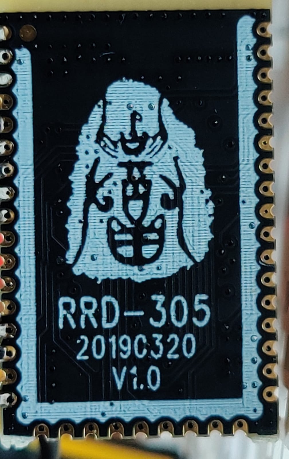
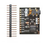
got a bunch of RRD-305 boards with QCC3005 on them.
Tried to get them running in a minimal test environment:
As with almost all those China boards: extrem little documentation available.
THX, Josef
Hi folks, it´s me with a second challenge (for the same project):
got a bunch of RRD-305 boards with QCC3005 on them.


Tried to get them running in a minimal test environment:
- 3.3V on VBUS
- 3.3V on POWER_EN
- SPI_PCM low
- LEDs (via resistors) at the LED pins
- no LED at all
- 1.8V output remains at 0.1xxV (means, the internal voltage regulator doesn´t get enabled? And therefor the whole chip is power down?)
- no pairing
As with almost all those China boards: extrem little documentation available.
THX, Josef
QCC3008 factory firmware dump
Hello jjs62,
I have two different QCC3008 boards here. Factory firmware dumps are attached. Maybe the I2S version is helpful for your project (tough it seems to be I2S output).
Hello jjs62,
I have two different QCC3008 boards here. Factory firmware dumps are attached. Maybe the I2S version is helpful for your project (tough it seems to be I2S output).
Attachments

Dear folks,
trying to connect QCC3008 (=slave) via I2S to a DSP (=master), I somehow did something wrong to the QCC.
Before changing to I2S, it did work nicely (receiving and sending audio analog in/out - bluetooth). Also connecting to all of the softwaretools worked quite fine.
Here comes the problem (me?): in ADK configuration tool, I tried to enable the QCC I2S interface as slave output and wrote this via the CSR USB-SPI to the board.After that,
I did not hook up a I2S master so far.
- connecting the board via bluetooth is not longer possible
- both LED are permanently on
- no connection to ADK conf. tool (timeout error comes up)
- PStool is still working
SPI_en low/high no difference.
The adapter board itself is a HY5300 (see jpg), pretty similar to the one, TeHSiggi is using
https://abload.de/image.php?img=qcc3008boardw3jhe.jpg
Now my questions to you all:
- how can I reset the board to factory defaults? I loked myself out from ADK conf. tool and can not switch back to the previous config.
- If I need to flash the board with factory default firmware, where do I get this? I made a dump with ADK conf. tool before changing config, but I guess, that doesn´t help too much. Sorry no PStool dump made.
Grateful for any help!
- For the long run: any idea what went wrong?
- When put in I2S slave mode, is it a must to have the master be present to even connect to the board via bluetooth?
Best, Josef
Hi, let me share with you my experience.
1. About reset this board to factory defaults, first you need to create a factory dump before any changes and this is only one way to back as I know. If you add changes for example with power and as a result, the module doesn't turn on anymore, the module becomes a dead body. Unfortunately, I have a lot of dead modules during my experiments with settings. And one more thing, this module has a reset button, but this button just reset all settings like device connection, history, etc. this is not a factory reset button.
2. I have a QCC3008 module and DAC PCM5102A. I wrote chinese sellers about how to connect this Bluetooth with that DAC, they told me that by default this module works with analog output and with digital (I2S) at the same time. I connected BT and DAC and I didn't get any results.
Maybe someone has this experience QCC3008 and PCM5102A? Could you share that with me?
Thanks.

@German1212
My board has I2S Master output enabled (in parallel with DAC out). Can monitor the I2S signals on logic analyzer nicely. Test with ext. DAC to be done.
For my project, I need I2S Slave output for conneting to ADAU1701 (as far as I read). Setting 3008 in slave mode, I crashed the module last time. Will retry in a few moments. Fingers crossed
Best, Josef
@German1212
My board has I2S Master output enabled (in parallel with DAC out). Can monitor the I2S signals on logic analyzer nicely. Test with ext. DAC to be done.
For my project, I need I2S Slave output for conneting to ADAU1701 (as far as I read). Setting 3008 in slave mode, I crashed the module last time. Will retry in a few moments. Fingers crossed
Best, Josef
This is interesting, in the case of external DAC PCM5102, what is a mode I need for QCC3008? Master or Slave?
And as I understood by default this board has a master mode, right?
Can´t say, whether all those boards are configured ex factory to send data as I2C Master. Meine is/was.
QCC3008 -> 5102: QCC needs to be the master (as far as I know)
Best Josef
QCC3008 -> 5102: QCC needs to be the master (as far as I know)
Best Josef
Hello
CSR8675 on BTM875-B board. I am using ADK4.4.0.21.
xIDE has successfully compiled the "VM_Speaker" code.
The ADK Configuration Tool can read the settings, but refuses to write the changes with an error: "Fatal Error: Unable to write configuration block 33 to the device.
The error code from the AHI was AHI_ERROR_INVALID_MESSAGE "
What could be the reason? can you share the Project Properties VM settings?
Hello
CSR8675 on BTM875-B board. I am using ADK4.4.0.21.
xIDE has successfully compiled the "VM_Speaker" code.
The ADK Configuration Tool can read the settings, but refuses to write the changes with an error: "Fatal Error: Unable to write configuration block 33 to the device.
The error code from the AHI was AHI_ERROR_INVALID_MESSAGE "
What could be the reason? can you share the Project Properties VM settings?
First of all, use BlueFlash to first dump your complete Flash content. If something goes wrong, you'll be on the safe side of things.
Second: Have you tried ADK 4.3.15? I had my issues with 4.4, that's why I switched back to 4.3.15 which works most stable for me.
Here are the settings from my TWI Sink application, that should match yours pretty much:


Second: Have you tried ADK 4.3.15? I had my issues with 4.4, that's why I switched back to 4.3.15 which works most stable for me.
Yes, i tried ADK 4.3.15. But in standart example sink "vm_speaker" program does not to start properly.
all of params of project such as your.

Can´t say, whether all those boards are configured ex factory to send data as I2C Master. Meine is/was.
QCC3008 -> 5102: QCC needs to be the master (as far as I know)
Best Josef
I have a result, and maybe for someone, this information will be useful.
I have two modules Bluetooth - QCC3008 and DAC - PCM5102:
On the QCC3008 module I didn't change any settings, by default this module has two output signals Digital and Analog.
The important thing is connection:
PCM5102 ----- QCC3008 connection:
VCC ----- x
3V3 ----- 3V3
GND ----- GND
FLT ----- x
DMP ----- x
SCL ----- x
BCK ----- CLK
DIN ----- MISO
LCK ----- CSB
FMT ----- GND
XMT ----- 3V3
SPIPCM (on QCC3008) ----- GND
After this connection, everything started working in my case.
I hope this information will be useful.
Thanks.
Attachments
In the meantime, I found out, how I crashed my modules:
By setting Configuration Set > Audio > I2S Plug-in Type to "Qualcomm SSM_2518 development board" in ADK conf tool
How do I get a "Customer developed plug-in"?
Do I need one at all?
If so, where should I put it?
Sorry for many dump questions!
Best,
Josef
By setting Configuration Set > Audio > I2S Plug-in Type to "Qualcomm SSM_2518 development board" in ADK conf tool
How do I get a "Customer developed plug-in"?
Do I need one at all?
If so, where should I put it?
Sorry for many dump questions!
Best,
Josef
Confused chinese documentation for RRD-305
Hi Josef,
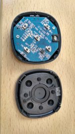
I can see (from your photos of the RRD-305) that the connections are not on the right side. I had the same idea as you (because, the doc is confusing) but I checked the GND (with the GND of the windond chip) to make sure, and I noticed that it is on the left side view from above.
The RRD-305 works well but only in analog output, the I2S does not work (on the v1.2 that I have) :-(
The goal is to use it as an input to the DSP of my amplified speakers, I also ordered a BTM305 in case, I hope it will work as specified, I was able to choose the I2S option on that one .
Hi folks, it´s me with a second challenge (for the same project):
got a bunch of RRD-305 boards with QCC3005 on them.
https://abload.de/image.php?img=3005rt7j2j.jpg
https://abload.de/image.php?img=3005fsejmz.jpg
Tried to get them running in a minimal test environment:
The boards (test three of them) do simply nothing:🙁
- 3.3V on VBUS
- 3.3V on POWER_EN
- SPI_PCM low
- LEDs (via resistors) at the LED pins
Any hint, what could be missing?
- no LED at all
- 1.8V output remains at 0.1xxV (means, the internal voltage regulator doesn´t get enabled? And therefor the whole chip is power down?)
- no pairing
As with almost all those China boards: extrem little documentation available.
THX, Josef
Hi Josef,
I can see (from your photos of the RRD-305) that the connections are not on the right side. I had the same idea as you (because, the doc is confusing) but I checked the GND (with the GND of the windond chip) to make sure, and I noticed that it is on the left side view from above.
The RRD-305 works well but only in analog output, the I2S does not work (on the v1.2 that I have) :-(
The goal is to use it as an input to the DSP of my amplified speakers, I also ordered a BTM305 in case, I hope it will work as specified, I was able to choose the I2S option on that one .
Hello I have a question.
Which of these two programmers will be good for you to buy Aliexpres.
CSR Bluetooth burner USB do SPI downloader narzędzia produkcyjne chip moduł Bluetooth z oprogramowaniem programistycznym|Demo Board Accessories| - AliExpress
CSR Bluetooth burner USB SPI S 1.8V pobierz programowanie narzędzia do programowania debugowania|Replacement Parts & Accessories| - AliExpress
It is important that it cooperates with all CSR software and does not cause problems. Or maybe you offer another type ?
I have two BTI 031 transmitters, I would like to reconfigure them to be able to pair both (TX & RX) in APTX-LL mode. Nominal does not have such support in transmitter mode APTX-LL.
Will it be without a problem ??
Greetings.
Attachments

- Home
- Source & Line
- Digital Line Level
- CSR8675 programming guide w software and tons of CSR info