You want solder to flow all around the tab and pad on both sides. It can help to touch a small amount of solder between the iron tip and the tab (or the pad) as you are heating the joint to improve heat transfer from the iron, then once a small amount of solder starts to melt into that location move the solder around to make sure solder flows everywhere you want it to go. Again, its something you practice to learn from.
If you still have the old dac board with the poorly soldered RCA connectors, try using your solder wick and maybe a bit of extra flux to clean up the old solder. Then try soldering them properly, getting solder to flow on all sides of the tab and down into the hole. Again, you can apply more solder to an area that isn't getting as much as you think it should. You don't necessarily need to move the iron for that if you have the joint hot enough, just move the end of the solder wire to the spot that needs more solder. The solder should easily melt and flow into place there, wetting the metal to be joined and forming a meniscus. It shouldn't turn into a big ball unless you add too much. If that happens, then wick some off.
With a tab (or maybe a pin header pin, etc.), sometimes it can help to wiggle the tab a little using the solder iron tip to apply more then less contact pressure repeated a few times in a wiggling motion. It can help encourage solder to wick down into the PCB hole. Practice, practice, practice. Only way to learn.
Last edited:
I will certainly be practicing before attempting the next step. The difference between my first and second board is night and day, and that is due to practicing the advice I've received so far.
I was wondering, though, what the pros and cons would be to separating the RCA jacks from the board and simply soldering a wired connection from the PCB to the RCA jacks. This seems like it would be easier to do, and it would make it easier to house the assembly. For example, I could try and find a cheap receiver with enough female RCA jacks at Goodwill or on Craigslist and use the pre-existing holes, if not the jacks themselves instead of trying to find, create, or modify an enclosure that will work with this current design.
I was wondering, though, what the pros and cons would be to separating the RCA jacks from the board and simply soldering a wired connection from the PCB to the RCA jacks. This seems like it would be easier to do, and it would make it easier to house the assembly. For example, I could try and find a cheap receiver with enough female RCA jacks at Goodwill or on Craigslist and use the pre-existing holes, if not the jacks themselves instead of trying to find, create, or modify an enclosure that will work with this current design.
If you put the board in a box and want to use preexisting holes for panel-mount RCA jacks, it should be no problem even if you install the PCB-mount jacks on the board. You can just solder wires for the panel-mount jacks to the PCB in parallel with the PCB mount jacks. It won't hurt anything.
Thanks, everyone. I've managed to correctly build this out, and everything on that end seems to be working well. Once I can get through this last step, I'll do some before and after measurements and try and write up everything I did to implement my active system.
My current issue is getting this to work on the computer I plan to use for this DAC, and I think the issue is related to the USB ports on the computer itself (Linux machine running Ubuntu Server). The current sound quality is very poor and the channel levels are inconsistent with some not playing at all. Initially, it did not work at all and the computer would not recognize the DAC unless I powered the DAC up after turning on the computer. This fix required making changes to USB settings the BIOS. I tested this on a Windows laptop and everything worked fine when plugged in, but I ran into similar issues of the DAC not being recognized or not playing if I ran the laptop on the battery.
Is it possible the USB ports are under powered? If so, is there a fix for this, or do I need to consider a different machine? If not, any thoughts on what the issue could be? (Also let me know if this is better discussed in a different thread.)
I tested this on a Windows laptop and everything worked fine when plugged in, but I ran into similar issues of the DAC not being recognized or not playing if I ran the laptop on the battery.
Maybe you are missing a ground for I2S?
Which USB card are you using?
If using diyink USB board, you may have to buy a paid Windows driver to get full features.
If using I2SoverUSB board, do you know how to hook it up?
If you can post clear, hi-res pictures it might help to understand what you are doing at this point.
I'm using the USB board and paid for the Windows driver since it's easier to test on a laptop. But in the end, the issue was pretty dumb. I didn't account for the channel mapping on this device which is why everything sounded so off.
I've seen I2S projects for Raspberry Pi's, but is that possible on all machines, and are there advantages to doing that?
I've seen I2S projects for Raspberry Pi's, but is that possible on all machines, and are there advantages to doing that?
Regarding USB from a PC verses RPi I2S or RPi USB, personally I prefer to skip the RPi. That said, some people really seem to like it since it doesn't require a big PC.
Also, there are some special use cases where I might want to use RPi too. In such a case I would likely prefer its USB, since the I2S is pretty jittery. Of course, the I2S jitter can be cleaned up but it costs money to do it. Iancanada (in the forum here) makes a thing called FIFO_Pi which can clean the jitter well.
Also, there are some special use cases where I might want to use RPi too. In such a case I would likely prefer its USB, since the I2S is pretty jittery. Of course, the I2S jitter can be cleaned up but it costs money to do it. Iancanada (in the forum here) makes a thing called FIFO_Pi which can clean the jitter well.
Is the I2S jitter specfic to the RPi, or is it common to all?
Although I really like the idea of one, I don't use a RPi, either, but that's based on my experience with the RPi 2. Mine was very unstable, especially over long periods of time, and I don't think it has enough processing power to run DSP on six channels at once. It's possible that's been cleaned up since then, of course.
Although I really like the idea of one, I don't use a RPi, either, but that's based on my experience with the RPi 2. Mine was very unstable, especially over long periods of time, and I don't think it has enough processing power to run DSP on six channels at once. It's possible that's been cleaned up since then, of course.
RPi is not for running heavy DSP, just as a simple player or as a 'bridge' between a more powerful DSP computer and dac.
Jitter is hard to get very low and easy to make worse. Some USB boards have very low jitter, such as I2SoverUSB, but it needs to be carefully connected to a dac board using very short length wires and a preferably a ground wire for every signal wire, if not careful jitter will get worse with improper wiring to the dac.
Jitter is hard to get very low and easy to make worse. Some USB boards have very low jitter, such as I2SoverUSB, but it needs to be carefully connected to a dac board using very short length wires and a preferably a ground wire for every signal wire, if not careful jitter will get worse with improper wiring to the dac.
An typical oscilloscope isn't going to do much good for looking at jitter.
I would suggest there are a number of other things you might need to worry about more first: (1) power supplies, and (2) access to dac chip control registers (not necessarily in that order).
Also regarding oscilloscopes, they are good for many things. Maybe the next most used instrument after a DVM. Very helpful to have for troubleshooting, for one thing. Have to learn how to use one though, a lot more to it than a DVM.
Regarding power supplies, what are you using now?
What are you using for an amplifier? Speakers?
Can you do a little computer programming?
Last edited:
My set-up is essentially built from Craigslist. My speakers a weird pair of bookshelf speakers (Usher S520, I believe) paired with a matching woofer (SW-520?). The amp is an ADS PH-6, and the pre-amp is a McIntosh MX-119. The DAC's power supply are also from DIYINHK (3.3 V and https://www.diyinhk.com/shop/audio-...e-dac-power-supply-regulator-91215v-15a2.html. This is all being run through an UPS Amazon was selling for almost 50% off.
My question about measuring jitter was more about the coolness factor. As you alluded to earlier, using I2S probably wouldn't help much, if at all, but I think it would be fun to be able to do those measurements and compare different pieces of equipment. I am beginning to get an understanding of how that data transfer works and find it interesting even if there's not a lot of audible difference.
However, I am more than open to making upgrades in other places if they are likely to be beneficial. I can do some programming, and more importantly, I know how to find answers to my programming questions so a project that goes down that route would be fun and educational, as well. Likewise, if there are some tweaks to my DAC board, power supplies, or other components, I'm sure I'd enjoy those, as well.
Any recommendations on an o-scope? I took a basic circuits course a few years ago to try and learn a little (managed to forget 95% of it), but we did use o-scopes so I at least have some familiarity with them.
A standard more or less average lab or test bench scope is 100MHz bandwidth, 2-channels. You can look around to see if there is one that catches your eye and maybe we can talk about if it is good. If that is too expensive, we can talk about lower cost options.
You can measure jitter if you want to, there is a really cool way that lets one listen to the jitter itself. About $50,000 for the rack of equipment to do it. Or, there is a much more limited thing called J-test which is really for SPDIF more than I2S since it looks for the deterministic artifacts that may tend to dominate SPDIF jitter. You would need a way to produce the test signal, a good ADC, and some FFT software. Then you just learn how to use it. Not that great for I2S but still can be useful if your jitter happens to be mostly of the stable deterministic kind.
To control the dac registers, an Arduino can be a good choice. We can help explain the hardware and software requirements to be able to do it. However, detailed discussion of register programming cannot be discussed publicly due to NDA restrictions on the information. There is some information around that might be helpful though such as by Dimdim, etc.
Regarding you playback system, its probably more or less on par with the dac you built. The dac can sound better if you get the output opamp +-15v supply off of any LDO regulators and powered by an old fashioned linear supply. The 3.3v LDOs from diyinhk are fine for most 3.3v things except for AVCC, which needs a particular type of linear power supply we can help you build.
I could pick up this one today and Siglent is pretty well reviewed. Any reason to keep looking?
Upgrading the power supplies and controlling the DAC registers both sound like fun projects, and I'd be happy to have y'all help me through both. I have an Arduino Uno that's never been used, and I think I would really enjoy getting going down this route since it combines software and hardware. I'll admit I don't know what it means to control the DAC registers, though, and searching hasn't been much help since the results assume you already know what a DAC register is. In other words, I don't even know how to get started on this one.
On the power supplies, did you mean a +-12V supply? I also realized the link for my +-12V supply didn't update so I'm putting it here, but it's essentially the same as the +-3.3V. Do you know of any resources or good search terms on how the choice of power regulator type can impact your circuit? I had assumed it was all roughly the same - so long as you can supply a constant voltage, the rest of the circuit wouldn't matter.
I was thinking I could work off of these boards and read through the links on that page to figure out what I need. Once I do that, I can run that by everyone here and make sure I'm on the right track.
But again, I really do appreciate all the time and support from everyone here. This has been a lot of fun, and I couldn't do it without this forum. Like I've said before, the final audio quality isn't really the biggest factor for me. I just enjoy tinkering and (very slowly) learning how the various pieces come together. I'm sure I'd save a lot of money and have a better final product if I just went out and bought new, quality gear to begin with, but what's the fun in that?
Any reason to keep looking?
The scope should be fine. You might want to do some reading:
http://ecelabs.njit.edu/student_resources/XYZ-Scope.pdf
https://download.tek.com/document/02_ABCs-of-Probes-Primer.pdf
Upgrading the power supplies and controlling the DAC registers both sound like fun projects, and I'd be happy to have y'all help me through both.
You should carefully study the old document from ESS:
http://www.esstech.com/files/4514/4095/4306/Application_Note_Component_Selection_and_PCB_Layout.pdf
For ES9028PRO it should work to use two AD797 for the AVCC supply they recommend (one AD797 for each of the two L/R AVCC channels).
For +-12v (+-15v), and old 7815/7915 regulator board should work fine, although it will need pre-regulation or pre-filtering to attenuate AC line harmonics.
Best to use R-core transformers which you can find on ebay or aliexpress. They take some time to ship from China, but that's the way it goes. They have very low coupling of HF/RF noise from the power line (a good thing). However, best to get one with two separate 15v or higher windings and two or three 9v windings. The low voltage windings can power the diyinhk regulators. The reason for higher than 15v windings is to allow some extra voltage drop across regulators and drop across any pre-regulation. Maybe 18v or 20v would be good. Depends on what you would like to do for about line harmonics.
I have an Arduino Uno that's never been used, and I think I would really enjoy getting going down this route since it combines software and hardware.
That's a 5v Arduino, which is fine, just means you will need an I2C bus level translator to interface with the 3.3v dac chip I2C port. Sparkfun has some you can use or I could suggest how to build one from scratch.
You might want to contact an ESS distributor for your geographic region to request a NDA form so you can get a data sheet for your dac chip. If unwilling to sign an NDA, it will be more difficult to get information, but maybe not completely impossible.
Will also send PM.
EDIT: Info on I2C bus: https://www.nxp.com/docs/en/user-guide/UM10204.pdf
Last edited:
I'm currently using torodial transformers from here - 15V for +-12V and 7V for the two +-3.3V. Since I plan to tackle the line harmonics, I'll need a higher voltage for the +-12V, but will I see much benefit going with an R-core transformer for the +-3.3V or bumping the 7V up to 9V? And what's the reasoning behind having an extra winding for each? (You mentioned having two windings for the +-12V and possibly three windings for the two +- 3.3V.)Best to use R-core transformers which you can find on ebay or aliexpress. They take some time to ship from China, but that's the way it goes. They have very low coupling of HF/RF noise from the power line (a good thing). However, best to get one with two separate 15v or higher windings and two or three 9v windings. The low voltage windings can power the diyinhk regulators. The reason for higher than 15v windings is to allow some extra voltage drop across regulators and drop across any pre-regulation. Maybe 18v or 20v would be good. Depends on what you would like to do for about line harmonics.
In either case, would this be a good fit? I need to do research on what I'll need to handle the line harmonics, but will the 18V or 24V transformers work, or should I look for a 20V transformer?
To make sure I follow, would this be used to build the circuit in Figure 4 of the pdf above and then feed 3.3V to each channel in the slots of the attached? Is the only difference in the AD797s here the mount? If so, the AD797ANZ would allow me to mount to a socket, right? Any reason to consider a different set of opamps than what I already have on the board (OPA 1688)?You should carefully study the old document from ESS:
http://www.esstech.com/files/4514/4095/4306/Application_Note_Component_Selection_and_PCB_Layout.pdf
For ES9028PRO it should work to use two AD797 for the AVCC supply they recommend (one AD797 for each of the two L/R AVCC channels).
That's a 5v Arduino, which is fine, just means you will need an I2C bus level translator to interface with the 3.3v dac chip I2C port. Sparkfun has some you can use or I could suggest how to build one from scratch.
Assuming it's not too difficult, I would prefer to build one from scratch. Doing so would help me get a better understanding of what's going on. If it is a lot of trouble to build, is this what I need?
Attachments
Last edited:
You don't have to change transformers if you don't want to. R-core are better than most torroids for preventing noise coupling from the AC line, due to the nature of their physical construction. I have seen custom designed torroids that perform very well, but not the stock ones. The custom torroids had dual electric field sheilds and mu-metal banding. The reason for separate windings is that it gives more options for voltage regulator upgrades and allows you to choose the best place to connect +-15v ground rails together. Choosing well can result in improved sound.
However, your existing audio system and dac board are of limited potential to begin with so no need going all out starting at this point. Your existing transformers should work if you want to keep them.
For line harmonics, if your transformer voltage is high but not too high you could simply put two sets of regulators in series, or you could put some stages of RC filtering between the rectifiers and voltage regulators. Better to skip inductor filters for this.
To mount SMD AD797 opamps in sockets you could use SOIC-8 to DIP-8 adapters. SOIC-8 to DIP Adapter - BrownDog Adapters - 970601
A template for an AVCC power supply can be found at: https://www.diyaudio.com/forums/digital-line-level/314935-es9038q2m-board-301.html#post5577605
...if not enough bass, you might need to add some bigger power rail filter caps near the AVCC opamps. Try to keep wires to the +-15v regulators short and of not too thin gauge.
Adapter boards for an I2C isolator chip if not available from Brown Dog can possibly be found at: Standard products for SMT and Leaded component prototype and breadboard
applications
Some I2C isolator ICs that might work: i2c Digital Isolators | Mouser
...or you could look at the isolators at Sparkfun and go to the documentation tab to see what chip or other parts and schematic they use.
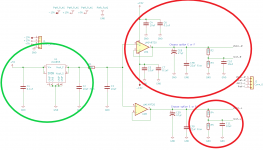
I am not quite clear on what the picture you attached is supposed to show?
However, your existing audio system and dac board are of limited potential to begin with so no need going all out starting at this point. Your existing transformers should work if you want to keep them.
For line harmonics, if your transformer voltage is high but not too high you could simply put two sets of regulators in series, or you could put some stages of RC filtering between the rectifiers and voltage regulators. Better to skip inductor filters for this.
To mount SMD AD797 opamps in sockets you could use SOIC-8 to DIP-8 adapters. SOIC-8 to DIP Adapter - BrownDog Adapters - 970601
A template for an AVCC power supply can be found at: https://www.diyaudio.com/forums/digital-line-level/314935-es9038q2m-board-301.html#post5577605
...if not enough bass, you might need to add some bigger power rail filter caps near the AVCC opamps. Try to keep wires to the +-15v regulators short and of not too thin gauge.
Adapter boards for an I2C isolator chip if not available from Brown Dog can possibly be found at: Standard products for SMT and Leaded component prototype and breadboard
applications
Some I2C isolator ICs that might work: i2c Digital Isolators | Mouser
...or you could look at the isolators at Sparkfun and go to the documentation tab to see what chip or other parts and schematic they use.
I am not quite clear on what the picture you attached is supposed to show?
Last edited:
Hi Mark,
You can probably ignore the picture I attached. I don't understand how the AD797 and AVCC circuit fits into this so I was trying to figure that out. Are you suggesting I switch out my current opamps with the AD797 and use the AVCC template for my 3.3V power supplies?
I got a I2C Digital Isolator chip and have a breadboard I can use to communicate with the DAC chip. What's the next step here?
I have also ordered a 7812/7912 regulator which I can run after my current regulator (after adjusting it to output 15V).
...I don't understand how the AD797 and AVCC circuit fits into this so I was trying to figure that out. Are you suggesting I switch out my current opamps with the AD797 and use the AVCC template for my 3.3V power supplies?
AD797 can be mounted on SMD to DIP adapters and plugged into sockets on your dac board. The are very good opamps, although expensive.
For ESS Sabre dacs, AVCC is a very particular type of power supply load. It should have a power supply that is good in ways good audio power supplies should be and that is very linear in its subtle regulation properties. It will affect the sound of the dac a lot. Most of the other power supplies are much less critical for sound quality.
Therefore, ESS recommended an opamp buffer circuit in a document from their website that I may have linked already. Just in case not, here it is: http://www.esstech.com/files/4514/4095/4306/Application_Note_Component_Selection_and_PCB_Layout.pdf
I would suggest building an opamp buffer supply as ESS wrote about and like the schematic I pointed to previously (if you feel up to building such a thing).
I got a I2C Digital Isolator chip and have a breadboard I can use to communicate with the DAC chip. What's the next step here?
You need an MCU such as maybe an Arduino to talk to the dac chip. There are solder vias on the dac board you have to connect the I2C isolator. The dac board does not include pullup resistors to the digital 3.3v power supply to the dac though. Typically they would be maybe 4.7k, but the isolator you got may already have pullups, not sure. You should sketch up a schematic of what you intend to hook up. Then you can assemble parts from that as your reference.
Quoting* "I would suggest building an opamp buffer supply as ESS wrote about and like the schematic I pointed to previously (if you feel up to building such a thing)".
I say this a lot, but I appreciate your willingness to walk me through this as I continue to work my way through understanding. I think I now follow the intent and design of the buffer supply in the ESS document. Let me know if any of this is incorrect:
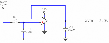
I could power this circuit using my existing +3.3V power supply as the DVCC 3.3V input in the ESS circuit diagram. Another option would be to use the left portion (green circle) of the circuit diagram you referenced from a different thread with that circuit being fed a 5V A/C signal. Is there any advantage to one over the other? And should ignore the AVCC-R portion of the thread's circuit as well as the final resister/capacitor portion (red circle)? These don't appear in the ESS document, and I'm assuming the thread's circuit has different functions than mine.
Three dumb questions:
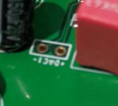
1) How do I identify which of the two 3.3V inputs on my DAC board power the opamps? I assume this is the middle input in the picture since it looks as if the 'bottom' one powers the DAC microcontroller.
2) I could assemble this circuit on a breadboard, but it would look nicer and take up less space if I could put it on a PCB. Any idea on how I could go about doing this?
3) Any idea what the "-DAC+" inputs in board's picture are for?
Quoting: "You need an MCU such as maybe an Arduino to talk to the dac chip. There are solder vias on the dac board you have to connect the I2C isolator. The dac board does not include pullup resistors to the digital 3.3v power supply to the dac though. Typically they would be maybe 4.7k, but the isolator you got may already have pullups, not sure. You should sketch up a schematic of what you intend to hook up. Then you can assemble parts from that as your reference."
I have an Arduino Uno and plan to use that. I've haven't had the time to really look into this portion of it yet, so I'm going to put that on hold until I finalize my power supplies.
*When I use the quote feature, I get an error message saying the post is too long and contains something like 7,000,000 characters.
I say this a lot, but I appreciate your willingness to walk me through this as I continue to work my way through understanding. I think I now follow the intent and design of the buffer supply in the ESS document. Let me know if any of this is incorrect:
I could power this circuit using my existing +3.3V power supply as the DVCC 3.3V input in the ESS circuit diagram. Another option would be to use the left portion (green circle) of the circuit diagram you referenced from a different thread with that circuit being fed a 5V A/C signal. Is there any advantage to one over the other? And should ignore the AVCC-R portion of the thread's circuit as well as the final resister/capacitor portion (red circle)? These don't appear in the ESS document, and I'm assuming the thread's circuit has different functions than mine.
Three dumb questions:
1) How do I identify which of the two 3.3V inputs on my DAC board power the opamps? I assume this is the middle input in the picture since it looks as if the 'bottom' one powers the DAC microcontroller.
2) I could assemble this circuit on a breadboard, but it would look nicer and take up less space if I could put it on a PCB. Any idea on how I could go about doing this?
3) Any idea what the "-DAC+" inputs in board's picture are for?
Quoting: "You need an MCU such as maybe an Arduino to talk to the dac chip. There are solder vias on the dac board you have to connect the I2C isolator. The dac board does not include pullup resistors to the digital 3.3v power supply to the dac though. Typically they would be maybe 4.7k, but the isolator you got may already have pullups, not sure. You should sketch up a schematic of what you intend to hook up. Then you can assemble parts from that as your reference."
I have an Arduino Uno and plan to use that. I've haven't had the time to really look into this portion of it yet, so I'm going to put that on hold until I finalize my power supplies.
*When I use the quote feature, I get an error message saying the post is too long and contains something like 7,000,000 characters.
Attachments
- Status
- This old topic is closed. If you want to reopen this topic, contact a moderator using the "Report Post" button.
- Home
- Source & Line
- Digital Line Level
- Guide me through assembling DAC board?