I would really suggest to get the eval board first. It is designed so you can try alternate voltage regulators. You can get an LT3045 module and see if it makes any difference to dac performance. if not, maybe you don't need it. Or then again, depending on incoming power quality, it may need some cleaning up. Maybe LT3045 can do part of that. In other words, I think you are jumping the gun here. You should first figure out what matters a lot and what matters very little, then expend effort and board space where it is useful.
I think you are absolutely right, I am really champing at the bit here... I really wish that I could have a board right now, but it won't be available for another month. In the meantime, all I can do is study as much as I can.
That being said, I like to believe that some of this work will be useful, especially because of the desire to put so many components directly on the DAC board, instead of a separate board like is done by AKM for their evaluation board. And because I am dealing with pretty severe space constraints, I want to make sure that the overall design is feasible. In other words, if the NJM78M05 is enough and the LT3045 does not make any difference, I'll take that as a great piece of news (simpler design, cheaper BoM). But if we realize that using an LT3045 is the way to go, I want to make sure that the overall brick configuration can accommodate it, otherwise the whole stack falls apart.
Also, I really like the idea of having options that are not necessary but make the stack better, and the drop-in replacement of the NJM78M05 by the LT3045-78XX is a perfect example of such an upgradeable design, much like the fact that the Sitara SoM will be optional. Or the fact that the two mono DAC boards could be replaced by a single 4-channel DAC board, without changing much at all. In fact, I'll make sure that we design a single DAC board that can be used in both configurations by setting the right jumpers (assuming that we can do that without any degradation of our critical signals).
Finally, this exercise, while certainly premature, remains a good way for me to learn about many different components.
In the meantime, all I can do is study as much as I can.
In that case I would suggest to study things such as:
https://www.diyaudio.com/archive/bl...d1460406090-bruno-putzeys-micropre-g-word.pdf
Henry Ott's, Electromagnetic Compatibility Engineering
https://www.electronics-tutorials.ws/systems/feedback-systems.html
https://www.electronics-tutorials.ws/systems/negative-feedback.html
https://linearaudio.net/sites/linearaudio.net/files/volume1bp.pdf
The latter stuff is to clearly understand why amplifiers and voltage regulators can turn into oscillators, and how their regulator error amps interact with capacitors in the regulation loop. If you are going to be designing with parts like LT3045, you should have some familiarity with such topics. For a more through treatment a text on control systems engineering might be useful to study, at least to start with.
Last edited:
In that case I would suggest to study things such as:
https://www.diyaudio.com/archive/bl...d1460406090-bruno-putzeys-micropre-g-word.pdf
Henry Ott's, Electromagnetic Compatibility Engineering
https://www.electronics-tutorials.ws/systems/feedback-systems.html
https://www.electronics-tutorials.ws/systems/negative-feedback.html
https://linearaudio.net/sites/linearaudio.net/files/volume1bp.pdf
The latter stuff is to clearly understand why amplifiers and voltage regulators can turn into oscillators, and how their regulator error amps interact with capacitors in the regulation loop. If you are going to be designing with parts like LT3045, you should have some familiarity with such topics. For a more through treatment a text on control systems engineering might be useful to study, at least to start with.
Thank you Mark! Much appreciated. I will dive in right away.
The LT3045 is overkill for the supplies other than VREF and clock it would seem. I would use something relatively simple to replace the 7805s, like ADP7112 for example.
I'm starting to understand your point (and Mark's) better: the NJM78M05s are used for the VDD supplies, and as such are not as critical. The VREFs are handled by the Jung-Didden circuits, which we should not mess with. Therefore, we should not need the LT3045.
Sorry that it took me so long to understand that.
No problem
") .
. I actually think the LT3045 could be higher performance than the Jung variant regulator that AKM is using because of their choice of AD817 as the error amplifier. AD817 has some pros and cons, but it is noisier than LT3045 (LT3045 is 2 nV/rtHz at 1 kHz, while AD817 is 15 nV/rtHz. Would need to see complete measurements of that regulator, which don't exist.
Using their Jung style regulators is the safest bet still, if only because they have done it on the eval board. I would say that you do need to pay attention to their layout - it's not going to be any easier than LT3045.
No problem
I actually think the LT3045 could be higher performance than the Jung variant regulator that AKM is using because of their choice of AD817 as the error amplifier. AD817 has some pros and cons, but it is noisier than LT3045 (LT3045 is 2 nV/rtHz at 1 kHz, while AD817 is 15 nV/rtHz. Would need to see complete measurements of that regulator, which don't exist.
Using their Jung style regulators is the safest bet still, if only because they have done it on the eval board. I would say that you do need to pay attention to their layout - it's not going to be any easier than LT3045.
I totally agree.
A few questions:
1. Can I use the LM7805 as a replacement for the NJM78M05 without changing anything else to the circuit?
2. If so, is there any downside in using the SOT-223 form factor vs. the TO-263 form factor (besides the fact that DIY soldering would be harder)?
3. Is there any math that I can use to figure out the minimum ESR for C352, C357, C358, C361, or is testing the only option? The T59EE477M016C0020 gives us 20mΩ, while the T523H477M016APE070 gives us 70mΩ. Both are roughly the same price and have comparable footprints.
4. The NJM78M00 datasheet indicates that "the capacitance and the equivalent series resistance (ESR) influence [the] stable operation of the regulator," but this is related to Co, not Cin, which is 0.1μF in both the datasheet and the evaluation board. What would be an acceptable ESR value for this small capacitor?
In that case I would suggest to study things such as:
https://www.diyaudio.com/archive/bl...d1460406090-bruno-putzeys-micropre-g-word.pdf
Henry Ott's, Electromagnetic Compatibility Engineering
https://www.electronics-tutorials.ws/systems/feedback-systems.html
https://www.electronics-tutorials.ws/systems/negative-feedback.html
https://linearaudio.net/sites/linearaudio.net/files/volume1bp.pdf
The latter stuff is to clearly understand why amplifiers and voltage regulators can turn into oscillators, and how their regulator error amps interact with capacitors in the regulation loop. If you are going to be designing with parts like LT3045, you should have some familiarity with such topics. For a more through treatment a text on control systems engineering might be useful to study, at least to start with.
Mark,
These articles are absolutely awesome. I love Bruno Putzeys' no bs. tone! And his overall approach to grounding, differential circuits, and feedback loops make a lot of sense. Instead of the arcane wizardry of HiFi propellerheads, it just seems like solid engineering to me. I still have a long way to go before I can understand everything, and an even longer before I can really make his of this knowledge in any practical sense, but this will help me understand many pieces of documentation a lot better.
Thank you very much.
I totally agree.
A few questions:
1. Can I use the LM7805 as a replacement for the NJM78M05 without changing anything else to the circuit?
2. If so, is there any downside in using the SOT-223 form factor vs. the TO-263 form factor (besides the fact that DIY soldering would be harder)?
3. Is there any math that I can use to figure out the minimum ESR for C352, C357, C358, C361, or is testing the only option? The T59EE477M016C0020 gives us 20mΩ, while the T523H477M016APE070 gives us 70mΩ. Both are roughly the same price and have comparable footprints.
4. The NJM78M00 datasheet indicates that "the capacitance and the equivalent series resistance (ESR) influence [the] stable operation of the regulator," but this is related to Co, not Cin, which is 0.1μF in both the datasheet and the evaluation board. What would be an acceptable ESR value for this small capacitor?
I would just use something other than a 7805, they are ancient and low performance. The only advantage is cost.
There are 100s of parts that would meet your needs and be better probably, even if it they aren't necessarily going to compromise the performance. If you are going to make a statement design you might as well. Why did AKM use them? Probably to save a few cents and because NJM is a Japanese company. I've noticed Japanese companies love to use local stuff when they can.
Depending on how much current you need, you can look at simple fixed regulators like TPS7A80, LP5907, LP2992. There are lots of options that are designed to be stable with low ESR caps on the output because of the ubiquity of ceramic caps.
Sounds good! I'll go out and look for some options. The NJM78M05 has a 500mA guaranteed output current, so I must assume that we won't need more, and I'll look for something that can deliver at least that.
Last edited:
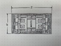
DAC PCB Sketch
Here is a very crude sketch of what the PCB layout could be for the DAC board with all regulators mounted on board (including the Jung-Didden circuits). The board is 70mm × 35mm, which means that 2 of them could be mounted side by side within a 80mm × 80mm brick. And by stacking two pairs within the brick, we should be able to provide 4 balanced mono outputs driven by 4 separate AK4499EQ chips, with 4 discrete power supply regulator circuits. And because we are planning to use low-profile tantalum capacitors, this brick should not be taller than 80mm, including the Sitara SoM, the PSU board (inspired by the OSVA AAPSU01), the isolated XMOS board, and the XLR connectors board. Such a brick would have a $1,200 BoM.
The four green boxes on the sketch outline four LT3045-78XX LDO regulator boards, which remain the simplest option for improving upon the NJM78M05. Again, this is probably overkill, but it is good to know that the design could accommodate this type of upgrade. And if these do make a positive difference, there is probably enough room to use four regulator boards with two LT3045 circuits mounted on each regulator board, thereby going from 500mA to 1.0A on each board, which would remove the need for any heatsink. It is also possible that we could find (or design) a low profile heatsink that would connect the four regulator boards together, thereby killing two birds with one stone: dissipating heat and improving the structural integrity of the overall assembly.
With this design, all transistors are mounted on the back of the DAC board, as done by the AKM evaluation board. Also, with such a densely-populated board, it is quite likely that we will have to go from a 4-layer PCB to a 10-layer PCB, but that's probably for the best anyway, and the cost increase should remain marginal when compared to the overall BoM (the 10μF or larger capacitors alone contribute to a heft $75 per DAC board, and so do the LT3045-78XX regulators if we decide to use them).
The board also includes 4 rows of 2.54mm headers with 2 × 12 pins on the short sides and 2 × 14 pins on the long sides, for a total of 52 pins. We've not done any pin assignment yet, but I am willing to believe that it will be enough. We might also break down these rows into subsections, with some mounted on top and some mounted underneath. And we might use different connectors for different signals and supplies, but it is good to know that we have enough real estate to get electrons in and out of the board.
The overall placement of components also reflects more or less what is done on the AKM evaluation board. The only main deviation are the C350 and C351 470μF capacitors for -15V and +15V, which are mounted on opposite sides of the AK4499EQ chip. These might be brought back together if necessary once we have a more precise placement of all the components (my little Moleskine notebook will only take us this far). I should also mention that all dimensions for the large capacitors were taken from this evaluation matrix.
Luckily, the proposed layout should make it possible to shield the DAC chip, 4 × OPA1612 OpAmps, 4 × 220μF capacitors, and 19 other capacitors within a 37.7mm × 25mm 3600637250S WE-SHC shielding cabinet. I am still not clear whether this would help or not, but it is good to know that we have this option.
Last but not least, this little DAC board should have a BoM of about $350 without the (probably overkill) LT3045-78XX regulator boards. Therefore, it should be applicable to many other DIY projects, which is quite nice.
Attachments
Last edited:
Last but not least, this little DAC board should have a BoM of about $350 without the (probably overkill) LT3045-78XX regulator boards. Therefore, it should be applicable to many other DIY projects, which is quite nice.
Correction: the BoM without LT3045-78XX regulators should be around $200.
...you can look at simple fixed regulators like TPS7A80, LP5907, LP2992.
Agree, at least for the digital supplies. For analog supplies, I would say perform listening tests and measurements before finalizing an alteration to the eval board design. If this were a low cost project I wouldn't worry too much, but an ultra-high end part like AK4499 needs some care to enable its intended performance level. An old part like 7805 doesn't actually sound too bad when used for analog audio. Don't know so much about all the new regulators on the market, but haven't had much success so far getting the best sound out of LDOs for analog circuits. That's not for having failed to try either. At the same time, I have not done an extensive effort. There is a paper at Linear Audio you might want to study: https://linearaudio.nl/sites/linearaudio.net/files/v4 jdw.pdf
Regarding capacitor choices, ESR may not be the only consideration. I don't have the desire to scour the eval board schematic looking for each capacitor you might ask about from the BOM. At a minimum, I would want to know where on the schematic it is used.
Last edited:
Regarding capacitor choices, ESR may not be the only consideration. I don't have the desire to scour the eval board schematic looking for each capacitor you might ask about from the BOM. At a minimum, I would want to know where on the schematic it is used.
I have added references to the capacitors on the evaluation matrix, as well as references to voltage levels on the BoM. Please let me know if there is anything else I can do in order to make these documents easier to read. I wish that I could annotate the schematic, but the document is not public yet.
Agree, at least for the digital supplies. For analog supplies, I would say perform listening tests and measurements before finalizing an alteration to the eval board design.
Agreed. And just to make it clear, I am not planning to make any alteration to the reference design at this point. Just planning to mount the NJM78M05 on headers so that we could easily swap them with the LT3045-78XX. And I will try to use the DIP version of the AD817 so that we could try alternative parts, but I am not positive that I will have enough space on the PCB to do that. It would be really nice though, and there is a good chance that we can do it, especially if we can afford to remove 8 pins on each of the 12-pin headers located on the short sides of the board.
within the brick, we should be able to provide 4 balanced mono outputs driven by 4 separate AK4499EQ chips, with 4 discrete power supply regulator circuits.
You may have to use separate I/V opamps for each of the four channels from each dac chip. If so, then it might be a fairly simple matter to software/hardware configure the brick for 4 mono channels or 16 normal channels. That assumes mono mode would simply sum mono I/V outputs to give lower noise. The connection between I/V outputs and a low noise summing amp would have to be very low noise, but it could possibly be switched in or out with small profile pin jumpers. Given what a brick would have to sell for, you might even sell a few if there are a reasonable number of channels that could be brought out on a small header or something for those that would prefer such a configuration.
Also, is that 4 discrete regulator circuits per brick or per dac chip? If the latter, then it might be more sensible to make 16 channels an option. If the former, you would probably be wise to test a mono dac configured that way and evaluate performance.
Last edited:
You may have to use separate I/V opamps for each of the four channels from each dac chip. If so, then it might be a fairly simple matter to software/hardware configure the brick for 4 mono channels or 16 normal channels. That assumes mono mode would simply sum mono I/V outputs to give lower noise. The connection between I/V outputs and a low noise summing amp would have to be very low noise, but it could possibly be switched in or out with small profile pin jumpers. Given what a brick would have to sell for, you might even sell a few if there are a reasonable number of channels that could be brought out on a small header or something for those that would prefer such a configuration.
Also, is that 4 discrete regulator circuits per brick or per dac chip? If the latter, then it might be more sensible to make 16 channels an option. If the former, you would probably be wise to test a mono dac configured that way and evaluate performance.
That's exactly what I was planning. On the attached picture, the four rectangles called "OPA" are the OPA1612 of the I/V opamps, and a brick will be able to contain four of these boards. So, with a single type of DAC board and nothing more than an Allen key and LEGO-like instructions (or IKEA-like, make your pick!), anyone should be able to assemble 1 × 1 bricks that offer the following:
- 1 mono channel driven by a single AK4499EQ
- 4 mono channels driven by a single AK4499EQ
- 2 mono channels driven by two AK4499EQs
- 8 mono channels driven by two AK4499EQs
- 4 mono channels driven by four AK4499EQs
- 16 mono channels driven by four AK4499EQs
The Sitara SoM will be optional and the BoMs for all the configurations will go from $200 (no Sitara, no LT3045) to $1,200 (Sitara, 16 × LT3045s).
Attachments

PSU and USB Boards for DAC Brick
Now that we have a (very preliminary) validation that we might be able to fit all the components we need for our DAC board on a 70mm × 35mm PCB, we should do the same for the PSU and USB boards. In order to save the vertical space required to stack two pairs of DAC boards within a single 1 × 1 brick, we will try to make the PSU and USB boards both 70mm × 35mm, allowing us to mount them side by side. This will be a challenge, but it should not be as hard as doing it for the DAC board. Here is why.
For the PSU board, all we need is a slightly-modified version of the OSVA AAPSU01 with an extra LT1965 for the +3.3V supply. This board is 80mm × 35mm and isn't particularly dense. Furthermore, it uses large connectors that could be replaced by smaller 2.54mm headers.
For the USB board, we will do something similar to this DIYINHK board, which is 50mm × 30mm. Our larger footprint will make it easy to mount a larger chip, and we'll go for the XUF232-1024-FB374, which is the largest XMOS chip currently available. I doubt that we'll be able to max it out, but since our 1 × 1 brick must be able to output 16 mono channels, better be safe than sorry, especially once we start playing with DSD512 and DSD1024.
We will start with the USB board, then move on to the PSU board. The overall layouts will be crude approximations, because we have yet to establish which pins we need and how the boards will connect to each other, but this should give us a useful starting point nonetheless.
Last edited:
...we'll go for the XUF232-1024-FB374, which is the largest XMOS chip currently available. I doubt that we'll be able to max it out, but since our 1 × 1 brick must be able to output 16 mono channels...
At high sample rates and with multiple channels you would likely max out USB2 before the XMOS chip. Then what?
At high sample rates and with multiple channels you would likely max out USB2 before the XMOS chip. Then what?
Glad that you're asking! I was thinking about that yesterday. The XMOS is using USB 2.0, but the Sitara SoM is using USB 3.x, and the carrier board for the Sitara SoM will include a USB hub. Therefore, we could theoretically have one USB board per DAC board, or try to cram two XMOS chips on every USB board, making the latter a dual USB board.
I'll play with different options.
Eventually, I would hope that XMOS will upgrade to USB 3.x or USB-C... USB 2.0 is quite ancient by now...
- Status
- This old topic is closed. If you want to reopen this topic, contact a moderator using the "Report Post" button.
- Home
- Source & Line
- Digital Line Level
- 8 × AK5578EN + 8 × AK4499EQ ADC/DAC Boards