the PRO and Q2M boards are very different, have different bottlenecks. i would range the mods according to their impact on sound:
1. 205R FB in I/V and high ohmic LPF
2. low impedance opamp power
3. low noise clock power
4. low jitter clock
5. low noise Vref
6. low noise and impedance AVCC
7. low noise digital power
you may have AVCC mod leading putting the regs directly on pins though. an unexpected thing was very prominent effect of the FB cap type. silver mica took over PP.
It's nearly January 2019 when I ordered the 9038q2m board just to see Jan 2018.
It's getting back to square one all over. I've now had 3 DACs through my hands in the last 10 months. All of them are good enough to enjoy. The project was to clear out some old parts, my parts bin is now growing again.
I need to see a psychiatrist.
...This is the same thing that ESS had outlined and it can be heard...
Is that documentation available?
...my parts bin is now growing again.
I need to see a psychiatrist.
 That's just the nature of the hobby, It's much worse going cold turky
")
It's nearly January 2019 when I ordered the 9038q2m board just to see Jan 2018.
It's getting back to square one all over. I've now had 3 DACs through my hands in the last 10 months. All of them are good enough to enjoy. The project was to clear out some old parts, my parts bin is now growing again.
I need to see a psychiatrist.
no worries mate
I will post more info and pictures in your thread. a piece of cake!I now think from this that the performance of a reg is largely affected by the incoming voltage feed in normal regs. Why? the results between the Sulzer and Super Reg and the results of putting on a better reg in front of the LDO on the 1794.
if the upstream reg has low impedance, which is flat in the audio range, what is the point to put anything downstream of it?
if the upstream reg has low impedance, which is flat in the audio range, what is the point to put anything downstream of it?
So I thought as well. It goes against what seemed logical normally .But thinking about it again. What is the role of the reg...when it regulates? Dropping to the prescribed voltage...yes. But is part of its work also to compensate for the imperfect upstream feed as well? Yes. What if it did not have to compensate for that aspect? That had me thinking and still thinking.
I put the super reg upstream because that is the way it is set up in the tiny dac board I use as a pretest mule. Again the real eye opening thing was essentially using the same op amp in two regs with two different topologies. The difference was not small. The difference far far exceeds the difference in op amps in the IV and line stages. The normal thing I had been doing in the past was to put a lower grade prereg in front of a final reg. But given the situation I did not and was surprised.
So there are two aspects happening. The regulation characteristics of the same op amp in different topologies. The installation of a better better reg in front of the LDO in already built boards.
I am a mech eng and business grad not an EE. So forgive my ignorance on these matters.
Last edited:
I've been away from this thread for a while and I'm wondering if anyone have found complete op amp IV stage which is easily modded to this dac? I hope someone have made a pcb for this dac by now..
Not exactly. There are schematics for an output stage board and an AVCC board here: https://www.diyaudio.com/forums/digital-line-level/314935-es9038q2m-board-301.html#post5577605
However, the boards are currently hand built, not printed circuits.
Some pictures of dac that has both boards attached and a few other things can be seen here: https://www.diyaudio.com/forums/digital-line-level/314935-es9038q2m-board-301.html#post5577671
https://www.diyaudio.com/forums/digital-line-level/314935-es9038q2m-board-271.html#post5546997
Although it sounds very good, I would not say all the designs at this point are finished and done. The remain a few little puzzles I am interested in, and eventually people might want to start cleaning it up more and doing some more experiments to find out if some mods are a little overkill, if others could be improved a little more, etc. Since progress is mostly through trying to use ESS recommendations or better, using generally good engineering practices, and experimentation to see what works and what doesn't. It could use some more iterations and eventually an array of test equipment in a lab somewhere to evaluate some things that could be better understood. Still, not bad at all. Makes a pretty nice dac. Lot of work though.
Last edited:
A week ago, Mark thought this thread was dying. Am I spicing it up enough?
Sure. More activity here than I have seen in awhile. Something different maybe to break up the same old stuff that people probably tire of.
Another thing that may provide for a break and some different activity is that I am expecting an Allo Katana v1.2 dac here for review pretty soon. They say they will be shipping it in the next batch. Take a week or so to get here from India when they do send it. Should be interesting. Most people definitely don't want to do all the work to mod one of these ES9038Q2M dacs like I have done. Too much work, although we have a small handful of determined modders who say they are going to do it. Anyway, Katana may be an alternate way to get a good ES9038Q2M dac board for a good price that still would need power supplies, so some room for individual customization and diy-ing. Once again we will do 3-listening tests and see what we find. Katana will be better than ever and my modded dac should be better than ever. Be interesting to see however it turns out, I would think. It will for me.
After that is over, I don't know what will be next. Maybe some of our modders will start finishing up their dac projects enough to start testing. That would be great. I want to make sure as best as I can they all end up with dacs they are very happy with and that sound really good.
Last edited:
Thanks for the reply Mark, but I hoped someone had found an ebay pcb or something half decent atleast. Making a full on pcb is bit too much for me. It's a bit strange that something like this doesn't exist since it could be a universal tool for making dacs and pre's.. A dual regulator board and a IV dual op amp board would be brilliant!
.... Again the real eye opening thing was essentially using the same op amp in two regs with two different topologies. The difference was not small.
the first thing to suspect if the opamp change in a reg makes a big difference in sound is that it generates. NE5534 are the primary suspects. one would need a 100mHz scope to catch it. or you can try to compensate it by soldering 68pF cap between 5 and 8 pins.
Back to dac modding project business. Ran another test today. Increased wire gauge for output stage opamp power pins. Was #30 wire wrap wire that was used for convenience. New wire is #18 (probably overkill, but I want to see what happens). Also, added two more caps, one to each of the +-15v rails. They are 10,000uf, 0.05 ohm ESR electrolytics rated for up to 2.5A of ripple current. Left external film caps still connected for now. Interestingly, sound quality was worse. It sounded like quite a bit more harmonic distortion. Checked power rails with a scope, output signals, and AVCC, but nothing I could see there. Replaced output stage opamps with LME49860. Distortion was still there. Removed AD797 and replaced it with LME49720. Problem fixed. AD797 didn't like the big, low ESR caps on the power rails, so it seems.
With that distortion fixed, remaining brightness that was partially remedied with external film caps is now fully remedied. However, still a little distortion of a different sounding type. Started reducing DPLL bandwidth, which when I could keep it stable very much improved the remaining distortion. It is sounding really good. I can hear more small details more clearly than before, such as reverb tails on vocals and other instruments. All the foregoing is without any harmonic distortion compensation in use.
Next activity will be to clean up digital power on the dac chip to see if it will help better stabilize lower DPLL bandwidth settings. The lower the better. Too bad I don't have a good way to measure jitter out of the AK4137 board and its clocks. However, will try the dac chip first to see if any improvement to be had there.
EDIT: Actually, I do have a jitter meter on loan from Richard Marsh. It doen't go down to ultra low jitter levels, but I should probably see if it can measure anything coming out of AK4137.
Last edited:
https://www.google.com/url?sa=t&rct...ttach=182582&usg=AOvVaw1L05L-8uC-pSRfvdm1U_Zk
February 1980. I reread this and the last paragraph was a reminder.
February 1980. I reread this and the last paragraph was a reminder.
Last edited:
Back to dac modding project business. Ran another test today. Increased wire gauge for output stage opamp power pins. Was #30 wire wrap wire that was used for convenience. New wire is #18 (probably overkill, but I want to see what happens). Also, added two more caps, one to each of the +-15v rails. They are 10,000uf, 0.05 ohm ESR electrolytics rated for up to 2.5A of ripple current. Left external film caps still connected for now. Interestingly, sound quality was worse. It sounded like quite a bit more harmonic distortion. Checked power rails with a scope, output signals, and AVCC, but nothing I could see there. Replaced output stage opamps with LME49860. Distortion was still there. Removed AD797 and replaced it with LME49720. Problem fixed. AD797 didn't like the big, low ESR caps on the power rails, so it seems.
With that distortion fixed, remaining brightness that was partially remedied with external film caps is now fully remedied. However, still a little distortion of a different sounding type. Started reducing DPLL bandwidth, which when I could keep it stable very much improved the remaining distortion. It is sounding really good. I can hear more small details more clearly than before, such as reverb tails on vocals and other instruments. All the foregoing is without any harmonic distortion compensation in use.
Next activity will be to clean up digital power on the dac chip to see if it will help better stabilize lower DPLL bandwidth settings. The lower the better. Too bad I don't have a good way to measure jitter out of the AK4137 board and its clocks. However, will try the dac chip first to see if any improvement to be had there.
EDIT: Actually, I do have a jitter meter on loan from Richard Marsh. It doen't go down to ultra low jitter levels, but I should probably see if it can measure anything coming out of AK4137.
The ESR as quoted of .05 is at what frequency? This is a interesting spec.
Why? you do realize the search for low ESR with caps is somewhat limited at audio frequencies.
https://cdn.shopify.com/s/files/1/1006/5046/files/V4_JW_F8.pdf
Some interesting calculators.
Wire Resistance Calculator & Table
https://www.eeweb.com/tools/wire-over-plane-inductance
( A nice find)
Oops! Sorry, Mike, you caught me there. Slight error reporting the ESR. Correct value is 0.053 ohms. https://www.mouser.com/datasheet/2/88/CKR_CKS_series-553026.pdf
Part number is 109CKS025M
EDIT: I have a pretty good multi-frequency LCR meter, but these caps have ESR too low for it to measure. However, when I measure elctrolytics they may vary some with frequency,
as f -> some caps have ESR that decreases and then starts climbing, and other caps just slowly increase, but usually the LCR meter is fine with them at 10kHz and has trouble at 100kHz. That's about what I would expect. Caps of this type often start becoming significantly inductive up there. Don't know exactly what AD797 didn't like, but they are known to have problems with caps over 4.7uf that are low ESR at all. Usually they require a small resistor in series with the cap. Didn't want to do that for the whole +-15v rails, so AD797 had to go.
Last edited:
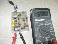
Well for this weekend I took out an old partially stuffed Sulzer Jung regulator, grabbed some parts I had since I discovered I had an LM385Z - 1.2V reference and made myself an op amp AVCC using an already soldered in NE5534. It is preregulated with an LT317. With the resistors I had on hand the closest combination I could come up with was 3.46V - still safe for the 9028PRO AVCC.
While this is burning in to ensure reliability before I put it on the ESS9028 DAC, I am using the test mule rig, a PCM1794.
While this is burning in to ensure reliability before I put it on the ESS9028 DAC, I am using the test mule rig, a PCM1794.
Attachments
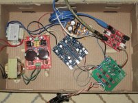
Interesting what you have there Mike. Not sure I will ever go that way for one of my dacs, but I do like the cardboard box prototyping setup. Would probably put some tape on there somewhere to hold the transformers in place, you just in case anything gets jostled.
Looks like I may be joining you soon in playing around with an ES9028PRO, which I am primarily interested in doing to see how it differs from ES9038Q2M in terms of best possible sound quality. The only reason I can think of is the 256-tap interpolation filter option (if I can come up with some coefficients), and maybe more dynamic range associated with lower noise which in turn is is possible because of the higher output currents.
Anyway, my diyinhk board came today. It is only populated with the dac chip and an SMD voltage regulator for the 1.2v supply. I think I will have to replace the regulator with a 1.3v version though. That makes 1 mod lined up already.
Since the board is undocumented (they say the schematic is printed on the board - NOT), I spent the afternoon sketching out the schematic, and already thinking about the 2nd and 3rd mods. The second will be to redesign the output stage, and the third mod would be to try to bring out wiring to access the dac output channels they didn't use. They have two outputs in parallel going to each I/V converter, which uses up 4 out of the 8 total channels. They tied the other 4 channel outputs together in twos like they did with the first four channels, but they didn't bring out any traces from the dac chip big enough to solder to (by most reckoning). Maybe I will see if I can test out my microsoldering skills on those very tiny pins. Two sets of pins will be easy, and the last to sets of parallel pins will be hard as it gets, I think. Biggest problem will probably be getting the solder to go where I want it. The low temperature leaded solder I use tends to want to form bigger drops than I want, maybe due to surface tension when it is molten. We'll see.
Attachments
Well Mark, you were correct in using an op for AVCC. My op amp based Sulzer blew the LT3042 out of the water immensely. Not even close.
A tip for followers. Don't waste your time on LT3042/ 3045s. Honestly, they might be low noise but they are SLOW in response and cannot deliver the goods at all.
The LT3042 are slightly better than the LT1963 and likely the LT1763 but they are not one what would consider good for AVCC. Definitely better than the AMS1117-3.3 LDO and don't even think about LT317s.
So based on my testing of the 5534 on the Sulzer then the Super Reg and then the LME49710 on the Super Reg on the test rig, there is a lot more to come. since this 5534 on the Sulzer is like really at the bottom of the heap. Parts bin selection of old caps, cheap resistors etc. I will begin building a Super Reg for AVCC using the LTC6655 1.25V.
I have yet to install the Super Reg on the IV stage, that will come in the next week as I dismantle the test rig to retrieve the Super Reg.
For those who don't want to build a Super Reg or Sulzer, there is something promising. I have ordered one and the topology should be very similar to the Sulzer. The nice thing is that it will provide a "decent" supply for the IV as well allowing you to bypass the LDO common stuff. HIFI DAC Power Board Fever DAC Power Supply Board +- 12V 5V replace LT1963AEQ | eBay
I've ordered one a few weeks ago and still awaiting delivery. We have a Postal Strike in Canada so I am expecting it to be delayed. There's a good chance for less than $30, you will get something half decent in performance without fabbing something if that is not your thing. Oh, because they are using all positive regs for +- supplies, you will need separate twin windings on the secondary for the 15V. Most of the chinese C core transformers and toroids are normally twin windings. Otherwise you can use two separate transformers which is a nice thing.
Last edited:
- Home
- Source & Line
- Digital Line Level
- ES9038Q2M Board