Next stage if to cut the legs off the left side LT1963. Then I can power up the other LT1963. If you look carefully at the first picture with the clock, I can remove that ferrite bead filter. I will then wire that in series with the output of the LT3042 and then take that wire to the crystal. That will then save me from cutting the trace leading to the clock as removing that filter will have the same functionality. This then allow me to separate the AVCC and clock from DVCC etc. That gains me some space. I will attach a small prereg to the input of the LT3042 board. This will save some board space as the LT3042 is too spacious. 1/3/5pcs DC Voltmeter LM317 Voltage Regulator Buck Converter Circuit Board | eBay
Last edited:
Yep. That looks to be pretty heavy gauge wire supporting it. I'm sure a lot of people would be interested to take a look at the insides of one. Good that you got it working. After that I would say you are probably getting increasingly qualified to work on small parts. If you can solder small enough little strands of wire, surprising some of the things you can fix.
Did I mention my eyes were hurting afterwards. I don't have those head magnifers you have. I ended up taking a look with a magnifying glass then "guessing" where it was ending up going. Whew!
These are the good magnifiers: Amazon.com : Carson Optical Pro Series MagniVisor Deluxe Head-Worn LED Lighted Magnifier with 4 Different Lenses (1.5x, 2x, 2.5x, 3x) (CP-60) : Sports & Outdoors (In general, seems like anything with a large number of Amazon reviews that average 4-1/2 stars is usually good.)
For this particular item: Good, clear focusing lenses, and a selection of magnifications that just snap into place. Highly recommended. Did most of my small work with these, and still do.
For this particular item: Good, clear focusing lenses, and a selection of magnifications that just snap into place. Highly recommended. Did most of my small work with these, and still do.
Last edited:
Here is the system as it is now.
Maybe a good idea to get those antennas, er, um, wires a bit more carefully routed and shortened to a not excessive length. Hard to say what all might be going on there otherwise.
Maybe a good idea to get those antennas, er, um, wires a bit more carefully routed and shortened to a not excessive length. Hard to say what all might be going on there otherwise.
This is interim until maybe the Christmas holidays or so.
Those antennas might pick up roon for free maybe. The long wires are really mostly transformer leads. Most others are as short as can be for the time being. In the end, they are going to be flat , wide and shielded.
Received email from Allo this morning. A Katana 1.2 dac is in shipment here. Supposed to arrive here from India by this Friday, assuming no delays along the way.
Don't know about other folks, but I'm excited to find out how it sounds. Review units are supposed to come with an isolator board, and both types of output stage boards. A number of different ways to power the stack will offer various opportunities to try to optimize sound quality. So far, best sound quality results are being reported with extensive linear power supplies. Good to know how good it can sound at its best, but the greater number and the higher quality of external power supplies can be expected to make the price range for a completed system quite broad.
At a minimum, adding one IFI 5v supply to power the dac board (and assuming one already has an RPi with its own power supply) would be expected to add about $50 to the cost getting up and running. On the upper side of the cost equation, we will have to see. So far, it looks like some people have a lot invested in power supplies reported to give the best sound quality. Not sure what we will end up doing here, but it should be interesting to see how things turn out. 🙂
Here is the system as it is now...
The ES9028 looks exactly like the 9038PRO, I wonder if it's the same board?
I must get my finger out and do something with it; too much work, it's getting in the way of my projects 😀
They have a newer board for ES9038PRO, although this board could be used for that if purchased without the dac chip, and change IV resistor and cap values.
Was just thinking about the modders who wanted to aim for a target date to have a fully modded dac all done by the end of the year, hopefully, and if possible, of course. If work actually got underway around the beginning of November, the interpolated completion target for around November 20th, or thereabouts, probably ought to be about 1/3 of the way to done.
Quite a bit to do to get going though, especially for those with a job and family, both of which demand lots of attention. (I recall many years of not having any time at all to myself except when I was in the car driving to work, and then back home later. Luckily, no cell phone then.)
My sort of worst fear is that nobody has started, or that disaster struck and expensive parts were lost, and no interest in starting up the project again.
Well, I don't suppose anyone would be willing to drop a brief note to the thread (or to me by PM) with a quick update, good or bad, either way is fine? If nobody will even answer at all, that would be the worst. It means people have stopped reading the thread, or stopped talking to me, bad either way I must say. 🙁
My modding has to be at a standstill till the next spring for a variety of reasons.
The DAC as it is now is sounding really really good. The worst fear is to do some and let the smoke out which is always a risk. Experience plays a large part when it gets to these stages and patience in double and possibly triple checking before it is plugged in. Fortunately, I can take my time and test the mods outside of the DAC before final assembly. I am now giving thoughts to final packaging and collecting bits of acrylic etc to create a vertical card cage arrangment in order to fit all the additional circuit boards that will be in the final DAC.
The DAC as it is now is sounding really really good. The worst fear is to do some and let the smoke out which is always a risk. Experience plays a large part when it gets to these stages and patience in double and possibly triple checking before it is plugged in. Fortunately, I can take my time and test the mods outside of the DAC before final assembly. I am now giving thoughts to final packaging and collecting bits of acrylic etc to create a vertical card cage arrangment in order to fit all the additional circuit boards that will be in the final DAC.
Hi Mark, yes still avidly reading the posts on this thread.
It is spring here so busy sowing and tending the crops.
Add to that our Southern Christmas happens in Summer ! ...
so lots of tidying ready for the influx of family and visitors over the long holiday break... schools get 6 weeks vacation and so parents and offspring can turn up at any time...
Trying to sift through the posts and the ever changing 'latest' mods is rather daunting....
Serge's thread is downloaded for a 'step A step B' recipe but that might happen next winter..... and while his thread lacks the desired I/V output stage, yours is rather scattered and, so far, beyond my ability to draw together and execute in a linear fashion.
Meantime I have purchased an Ess-9028Q2M dac that has I/V output and , when I get spare minutes, I'm shoehorning it and several other boards in to an old VCR chassis... pix to come.
Last edited:
Thank you, Mike. However, you are working on an ES9028PRO board, and I would really like to hear from ES9038Q2M modders, especially the group of people who wanted to see examples of though hole layouts, etc. I tried to help with providing some examples of that which hopefully would take some mystery or uncertainty out of how to proceed to make a modded dac.
I know I did skip through hole when I did the last few LT1763 regulators, but I figured by the time people got the AVCC and output stage boards done, and clocks swapped, they would probably feel confident enough to give the LT1763 regulators a try. If that is a hold up, or if it is seen as a reason for not starting, then someone needs to tell me that in plain English. I can try to come up with some alternatives if people don't think they will be ready for that by they time they would be getting to it.
I know I did skip through hole when I did the last few LT1763 regulators, but I figured by the time people got the AVCC and output stage boards done, and clocks swapped, they would probably feel confident enough to give the LT1763 regulators a try. If that is a hold up, or if it is seen as a reason for not starting, then someone needs to tell me that in plain English. I can try to come up with some alternatives if people don't think they will be ready for that by they time they would be getting to it.
Trying to sift through the posts and the ever changing 'latest' mods is rather daunting....
I think I responded to someone who said about the same thing recently.
Where things stand is that the schematics for the output stage and AVCC boards were posted by bih, then by MrSlim. MrSlim filled in a little information and changed the look of the schematics using a schematic drawing program. Those schematics and BOMs are the still the same. Nothing is changing there. Clock swapping is the same as ever.
I added some pictures of installing LT1763 regulators for the clock, VCCA, and then I added one for DVCC. The last one I tried didn't seem to make a noticeable difference. It would probably be okay to use one LT1763 for the clock and VCCA, which is what ESS does. So, the minimum would be one if someone would like to keep it to a minimum. I have three right now, so if someone wants to copy me exactly then it takes three. Pictures and explanations have been posted.
I have described my external 5v and +-15 power supplies. I described where I hooked up the 5v ground return wire at the digital end of the dac board. I described that the external 5v and +-15v power supplies only have grounds connected together on the dac board.
I have described my Arduino shield I use to connect Arduino to the dac chip. Various ways to connect to I2C bus have been described in detail and with pictures.
Recently I added some more filter caps to my +-15v supply, and to the output stage board. I posted the part numbers I used.
I also reported trying some external film caps on the +-15v rails. Don't know if they are still useful or not since I added more filter caps to the dac board.
I changed LME49720 (LME49860, same thing) to OPA1612 to reduce some harmonic distortion in the output stage that could have to do with some remaining RF from the dac, don't know.
I changed the AD797 opamps on a dual adapter on the AVCC board to a single plain old LME49720 at the time when I put the big filter caps on the +-15 rails, since AD797 didn't like that.
I have been experimenting with ways to help lower DPLL bandwidth, which I have posted about. I recommended using only gold plated or heavily gold flashed pin headers for I2S connections to the AK4137 board. Use gold pins the AK4137 board too to solder on a ribbon cable if you would rather. I ahve done it both ways. Had to repair some plated through holes on the AK4137 board after I removed the old non-gold pin headers. I wrote a post about that. Also use gold female pin connector for I2S connections. You could try using ufl connectors instead for I2S, but I haven't tried it yet. The change to gold is to reduce jitter which if not fixed will probably make getting DPLL bandwidth reductions more difficult. Reducing the bandwidth improves sound quality including among other things it makes cymbals sound very detailed and real.
I may try adding a filter between the dac outputs and output stage opamps inputs, but not happening right away.
I have started looking into external interpolation filtering with Spartan 6, but not very far with that.
------------------------------------------------
Okay, above the dashed line is a summary of pretty much everything I can think of.
What does it all mean?
I think it means you should:
1. build output and AVCC boards as already described.
2. swap in a Crystek clock
3. take steps to hook up either Arduino or RPi, if you want to improve performance by tweaking dac registers.
4. install somewhere around one, two, or three LT1763 regulators for the clock and VCCA, maybe for DVCC if you want.
5. maybe try OPA1612 opamps instead of LME49720. I have been using 'Brown Dog' DIP adapters so I can use SMD OPA1612 opamps in DIP sockets. Any brand adapter should probably work though.
6. depending on what kind of external power supplies you decide to use, you may need to add some extra filter caps on your output stage board or wherever you are bringing in your +-15v power.
That's about all you could do right now. To have an improved dac up and running you wouldn't have to do all of the above, but I would recommend doing at least 1,2, and 4. That will probably take you enough time that I may have some updated info on other things I am currently researching and experimenting with. I don't expect the I items I recommend starting with to change any more at this point. They are done.
If the above looks like something you would want to start on, and if you need specific page post numbers to find information on some mod, just ask. I will append to the post a copy of my current updated list of possibly useful or interesting posts. Using the 'find' function is a text editor program may make it easier to find posts you may want to look at.
Attachments
Last edited:
Serge's thread is downloaded for a 'step A step B' recipe.
Forgot to mention that I did make up PDFs with 'step A step B' for the output stage board and the AVCC board and attached them to posts in the thread. I think there may have been something that was too big to upload here that I am still hosting in my dropbox. Basically, I did exactly what was asked of me for those two boards.
I also wrote up some new information I discovered to make clock swapping easier and posted that here.
The main thing I did not do is I did not stop trying to learn more about making the best modded dac possible. I posted that the dac I described in great detail as requested sounds very good and that is still the case.
During the process of further work I found out some more things, but that doesn't change the fact that the posted dac modding build is a perfectly good revision level to build to. There is no reason not to. There always comes a point when a design has to be called complete and the next steps are taken to build and use.
Many commercial dac products offer improved 2.0 versions after some time has passed. What has happened in this thread is you have seen me continue to work on it, maybe towards a better model or something. Most commercial companies won't tell you what they are working on because they want to sell what they have now, not have people wait until the next thing comes out. By letting people watch as I continue to develop and learn they seem to have become confused that it will never be done or that it's too complicated or not documented well enough. Well, I think it was all documented and ready at the time I said to go ahead and build it. I just let you see what commercial companies don't let you see as I continue to work on new developments.
----------
EDIT:
Output stage instructions are here: Dropbox - Output Stage Instructions.zip
IIRC, The idea was to build the output stage first. As always, I hope people learn and gain confidence as they go. I think I said that after finishing the output stage, and given the AVCC board is so much easier, that people would probably find they no longer needed the same degree of detailed instructions and that the pictures and text posted in the thread should be enough to build an AVCC board. I think I also said if after building an output stage board if people didn't agree about the AVCC board that it was easy enough without a pdf, then I would make a pdf. I don't think one person ever actually built an output stage. There were problems and issues individual people had like wanting to wait until everything was fully cast in concrete so that only one order would ever have to made with mouser. So, that's why we have a schematic and BOM for the AVCC board. If people want to wait until I find out everything I might ever find out there will never be reason to make an order to Mouser.
If people want to order parts to make clock power regulators at the same time, it just takes an LT1763, a 1uf X7R input cap, a .01uf C0G noise cap, and a 10uf X7R output cap. I used SMD parts for the last two caps, but that doesn't mean you have to, you can used leaded parts too. They will work okay. There are pictures of how I did it a few pages back: https://www.diyaudio.com/forums/digital-line-level/314935-es9038q2m-board-301.html#post5577671 But, you could put the LT1763 on an adapter like we did for LTC6655. Or you could use an LT3045 moduie like Serge did. As I said, by the time you get to that point you should feel comfortable because you will have a lot more building and modding experience. If you don't feel comfortable by the time you get there, I will make whatever instructions you need, 'step A step B' so you can get it done.
The electrolytic filter caps that I added to the +-15v rails are given here: https://www.diyaudio.com/forums/digital-line-level/314935-es9038q2m-board-316.html#post5604175
But depending on what kind of +-15v power supply you decide to use you may or may not need them.
Last edited:
Has anyone done listening tests between an LT3042/45 and an LT1763/1963 powering the clock? Which is decidedly superior?
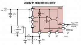
Probably using LT304x as a buffer for the LTC6655 3.3v reference on the AVCC board would be best for clock and VCCA. One shared regulator might enough, don't know. The schematic for that is shown below.
-----------
It might be good for AVCC too, maybe for an ES9038PRO board. The voltage divider would have to change, have to check the data sheet.
-----------
It might be good for AVCC too, maybe for an ES9038PRO board. The voltage divider would have to change, have to check the data sheet.
Attachments
Last edited:
Hello,
I bought same 3 rail PSU that Mikett mentioned before. It is specified as +-12V and 5V PSU. I just can adjust to a Maximum of 12,75V with onboard trimmers. Are there disadvantages to expect when running the opamps with a slightly lower voltage than +/- 15V?
not sure how to mod the PSU board to get a higher output voltage and if it will still be stable (guess it is just changing 2 resistors beside the trimmers, but no idea to which values...).
And to answer to Markw4 - got a lot of parts for my 2nd board I am starting to modify now. I decided to go the same way as on my first board for opamps on sockets and with "free" wired smd components (see my post #1289) but with new values and better 3,3Vreference for AVCC opamp stage. All layout-trials with surface-mounting on Surf- boards or breakoutboards for SOIC will have disadvantages regarding too less space for my components (SOIC boards with 1206 components) or too big board size (SURFBoards) to place them below the DAC board and too long wires for Vref. between the 3 surf boards.
Last edited:
For those who don't want to build a Super Reg or Sulzer, there is something promising. I have ordered one and the topology should be very similar to the Sulzer. The nice thing is that it will provide a "decent" supply for the IV as well allowing you to bypass the LDO common stuff. HIFI DAC Power Board Fever DAC Power Supply Board +- 12V 5V replace LT1963AEQ | eBay
Hi guys,
This looks great. Please tell us how it works when you'll receive it.
Is it 2A for the 3 outputs or 2A for each output?
What transformer voltage will be needed to acheive +-15v?
18v transformer?
thank you
3. take steps to hook up either Arduino or RPi, if you want to improve performance by tweaking dac registers.
Hi Mark,
I will start to mod my board soon.
As soon as I order and receive the katana 1.2 because the 9038q2m is my only music source for now... and I'm not so confident about my soldering skills 🙂
Will you share how to tweak dac registers using rpi?
PM me if you prefer.
thank you
Hello,
I bought same 3 rail PSU that Mikett mentioned before. It is specified as +-12V and 5V PSU. I just can adjust to a Maximum of 12,75V with onboard trimmers. Are there disadvantages to expect when running the opamps with a slightly lower voltage than +/- 15V?
not sure how to mod the PSU board to get a higher output voltage and if it will still be stable (guess it is just changing 2 resistors beside the trimmers, but no idea to which values...).
That is too bad.
The picture on the product page shows 5v to 15v.
But all other text shows 12v...
If you find a solution, please share it.
An externally hosted image should be here but it was not working when we last tested it.
- Home
- Source & Line
- Digital Line Level
- ES9038Q2M Board