It sure would be nice to have more info, but if ESS gives that to you they will presumably expect you to keep it all to yourself and not share anything here.
Yes, I am very aware of that. It will be a matter of what I can produce that will be of use to the DIY community without violating the NDA. Given the proclivity of Chinese manufacturers reverse engineering or cloning existing products, we could probably do the same with one of their boards as a basis for something that will require less "kudging"
Whatever happens on that, the hacked up Chinese DAC is working quite well, very close in sound quality to the Benchmark DAC-3 here, at least to my ears. As a point of reference here is a review including measurements of a DAC-3: Benchmark DAC3 HGC D/A preamplifier-headphone amplifier | Stereophile.com Also at Stereophile, the older DAC-2 made it to the recommended equipment list last year. Who knows, maybe DAC-3 will make it this year: Recommended Components: 2017 Edition Digital Processors | Stereophile.com
With respect to my Chinese DAC project as it stands now, I consider the DAC itself finished in terms of mods needed to get very excellent sound quality out of it. However, for anyone else interested in making one like it there may remain some issues and other considerations including: (1) a need to find another SRC and intersample-over solution (I can share the Arduino code I have for SRC4382 and SRC4392 chips), (2) a need for some kind of output buffer or headphone amp (the output op amp is loaded down too much if headphones are connected directly to the built-in stereo phone jack), (3) it would be nice to find a cheap way to get USB connectivity, and (4) I would like to find a suitable, but lower cost power supply than the Silent Switcher now in use. As time permits I am looking into some of the above items, but nothing specific to share yet.
Yes, I am very aware of that. It will be a matter of what I can produce that will be of use to the DIY community without violating the NDA. Given the proclivity of Chinese manufacturers reverse engineering or cloning existing products, we could probably do the same with one of their boards as a basis for something that will require less "kudging"
Good points, thank you. Might you have in mind to make a pcb to replace all the hand wiring? If something like that it would be great. I wouldn't want to do all that tiny fabrication again anytime soon, so easy to imagine others might be put off by it as well.
Also, there are some little power supply regulators that might be similar to what Silent Switcher does: TPS7A4700 Low Noise Power Module DC-DC 3-36V to 3V 3.3V 5V 12V 15V 1A Adjustable 699901905578 | eBay TPS7A3301 -5V -9 -12 -15V -18V 1A Ultra Low Noise LDO Negative Voltage Regulator 699924389058 | eBay Seems like the DAC needs high-quality power, so perhaps something like that would be a good fit. (and perhaps coincidentally, IIRC, brand 'B' DACs use HF switching power supplies
 )
)I'm liking the train of thought here. Is it possible to make a DAC where all the options of power lead out so that one can attach whatever power supply is available or developed. In other words make it so that the power themselves are OFF the DAC PCB. Also same situation for the IV converter. Make it so that one can attach any IV converter outside. Make this totally modular open to upgrading power supplies and IV circuits and maybe even clock. Then again, the circuit traces themselves might now be a good thing. I don't know.
But it would be a great platform to experiment on rather than hacking something tightly put together.
But it would be a great platform to experiment on rather than hacking something tightly put together.
Yes, that's very much I had in mind. I'm thinking that we can provide the footprint for basic power, I/O, and any other circuitry that would be required to create a stand alone working device, with connectivity for external/better supporting circuitry. The 9038Q2M isn't likely going to be the top of the heap but I think it is very good bang for the buck.
Yes, that's very much I had in mind. I'm thinking that we can provide the footprint for basic power, I/O, and any other circuitry that would be required to create a stand alone working device, with connectivity for external/better supporting circuitry. The 9038Q2M isn't likely going to be the top of the heap but I think it is very good bang for the buck.
Even if there was a DAC PCB with the Pro version of the 9038 that was modular, then I would purchase it immediately. I think the time for such a board is here. I'd hate to throw out PS supplies because a DAC was improved or vice versa. Same for IV circuits. Maybe I want to try a vacuum tube output instead of a transformer etc. Someone needs to make these things modular in some fashion.
Not modular, exactly. For this DAC to sound good all the mods are needed pretty much as they have been presented, which is for the most part essentially as ESS recommends (although a knowledgeable and experienced engineer might do some things a bit differently, depending on the design goals). My goal in this is to present for consideration the highest sound quality DIY DAC at the lowest cost and complexity people willing to work on it can figure out. It has its challenges as it is.
For one type of consideration, things like the oscillator really need to be located as close to the DAC chip as possible in order to maintain low jitter. The Chinese designers got that part right. In addition, it needs extremely high-quality power to sound its best. For that, it may be best to put the final +-15 low noise voltage regulators right on the board, or maybe leave a spot for some ebay units to be soldered in place (assuming they test out okay performance-wise).
Essentially, since there are already things like Buffalo DAC, which is highly modular, I would think of this as something more like a Model T of Sabre DACs, "you can have any color you want so long as it is black." Otherwise, performance goes down while cost and complexity go up.
There is no way I could hope to prove all the above to you unless you were to hear it for yourself, but this DAC can sound really, really good if people would only put off the impulse to toy around with it. That's something that can be done with any old DAC chip, no reason to use this one, and no way to make this one sound really good without doing everything just so, as it needs to be. That is just the kind of DAC chip it happens to be, not something changeable by us.
Thanks. Did some checking on the Buffalo DAC. Looks interesting seems exactly what I was looking for. For others to consider if the budget allows. Introducing the Buffalo III-SE-Pro 9028/9038
Despite of the fact that to do some mods you sould have some knowledge, I will try to help.
Indeed, AMS1117 have 3 pins - see datasheet. Namely, tab is the same connection as pin 2 (VOut). And at our board VOut trace is connected to tab (not to pin 2). Pinout of AMS1117 is:
1. Ground
2 and Tab - VOut
3. VIn
As I remember, in your small PCB with LT3045 pinout is the same as L7805 (for example, see datasheet too), i.e.
1. VIn
2. Ground
3. VOut
So, you need:
- desolder AMS1117
- place your PCB with LT3045 on original board somewhere near the L7805 (or 7808, it depends on version of original DAC)
- solder pin 1 of that PCB to pin 3 of L7805 in case of ver 1.06 (or L7808 in ver. 1.04)
- solder pin 2 of that PCB somewhere to ground (I think the simplest way is to do it via the existing hole to bottom layer)
- solder pin 3 of that PCB to the trace where tab of AMS1117 has been soldered
That's all. See also my picture in the post #336 for your reference (in that case pin 1 of my patch PCB is VOut, pin 8 is VIn, pins 3,6,7 is ground).
Hi,
I just received the LT3045 regulator in 3.3v.
Does some of you may check the attached picture and tell me if it is the right way to connect it?
Thank you.
Attachments
Hi,
I just received the LT3045 regulator in 3.3v.
Does some of you may check the attached picture and tell me if it is the right way to connect it?
That looks right. Just be careful that nothing on the new regulator PCB touches anything on the Chinese DAC board where something might short out. The LT3045 PCB needs to be mounted in some way so something like that can't happen.
Also, try to be careful removing the old voltage regulator. if you have any leaded 60/40, or even better 63/37, rosin core solder, sometimes adding a little of that to original solder can make it easier to remove with solder wick or with a solder sucker. Solder wick is usually the method of choice for printed circuit boards.
Last edited:
In either case, it clearly seems like your I/V isn't the culprit in the rather mediocre performance but the 9038 board, seeing as Victor is still getting better all-in performance (~-115 dB on the 3rd harmonic at 0 dBfs).
Still nice knowing these guys perform better in current mode. Also, the measurements are appreciated!
I found both 9018 and 9038 boards to perform at comparable levels after modification, using the same break out board with LM4592, using balanced current mode operation (pretty along much JensH's board).
The ES9018 board is slightly easier to modify, because through the removal of some tth caps, you can solder wires using their holes, in stead of soldering them on surface mount pads. Not a big deal though.
Furthermore, I found that the ES9038 board has higher than necessary distortion because of insufficient decoupling of the analog supply rail to the DAC. Mounting a largish cap underneath the board, using the pins that protrude from the board of the 47uF caps mounted above, brings significant improvements. You can improve low end distortion reduction by about 8dB, just by mounting 2200uF caps at this location.
The ES9018 board does not have this problem.
Hi Jens,
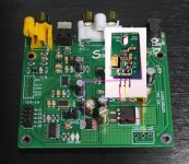
For good measure, I include two pictures of the board before and after the modifications.


I may feel inclined today to see if there is an optimum point for loading this chip. Perhaps some hybrid between voltage and current mode is the way to get better performance out of this board. Otherwise, the ES9018 board is just as good at 1/3rd of the price.
Note 1: opamp rolling in the standard board does not provide any measurable differences between the NE5532 the board comes with standard. I happen to believe this translates to no audible differences.
Note 2: why all this effort, shouldn't I get a life? As to the latter question, yes, please . As to the former: I ordered a nanoshark and now need four DAC boards to get some sound out. I have a PCM1794 board on it's way and will decide after investigating it. For the moment, the ES9018 board seems to be the better choice.
Note 3: I just went through the whole thread and concur with Peterma that unmodified, the 9038 board sounds somewhat harsh. Changing opamps didn't change that, but I may have been influenced by the measurements, which show no differences.
For good measure, I include two pictures of the board before and after the modifications.
I may feel inclined today to see if there is an optimum point for loading this chip. Perhaps some hybrid between voltage and current mode is the way to get better performance out of this board. Otherwise, the ES9018 board is just as good at 1/3rd of the price.
Note 1: opamp rolling in the standard board does not provide any measurable differences between the NE5532 the board comes with standard. I happen to believe this translates to no audible differences.
Note 2: why all this effort, shouldn't I get a life? As to the latter question, yes, please
. As to the former: I ordered a nanoshark and now need four DAC boards to get some sound out. I have a PCM1794 board on it's way and will decide after investigating it. For the moment, the ES9018 board seems to be the better choice.Note 3: I just went through the whole thread and concur with Peterma that unmodified, the 9038 board sounds somewhat harsh. Changing opamps didn't change that, but I may have been influenced by the measurements, which show no differences.
I found both 9018 and 9038 boards to perform at comparable levels after modification, using the same break out board with LM4592, using balanced current mode operation (pretty along much JensH's board).
The ES9018 board is slightly easier to modify, because through the removal of some tth caps, you can solder wires using their holes, in stead of soldering them on surface mount pads. Not a big deal though.
Furthermore, I found that the ES9038 board has higher than necessary distortion because of insufficient decoupling of the analog supply rail to the DAC. Mounting a largish cap underneath the board, using the pins that protrude from the board of the 47uF caps mounted above, brings significant improvements. You can improve low end distortion reduction by about 8dB, just by mounting 2200uF caps at this location.
The ES9018 board does not have this problem.
This is also our findings. You need extreme decoupling on the analog stage . We chose film capacitors (3) + 0.3F caps on each L and R analog stages. Big difference , especially for low frequency. Bass is incredible .
Not surprising about the decoupling if you look at the ESS downloads page: ESS Technology :: Downloads The "Maximizing DAC Performance..." document has a diagram on page 4 showing the recommended AVCC power conditioning circuit, along with a table of recommended op amps. ESS recommends separate AVCC power conditioning for left and right channels in order to help minimize any cross-talk.
To change the subject a little for anyone perhaps interested in further modifications, all I did with my particular Chinese DAC was generally clean up the power, use recommended AVCC conditioning, use differentially summed IV circuits similar to ESS recommendations, and install an ultra-low-jitter clock oscillator module.
In addition to changes to the DAC board itself, the board is powered from one of Jan Didden's silent switcher +-15v supplies, there is an external LME49600 headphone amp, and also an external hardware SRC. One problem I found with the silent switcher is that it can pass some input noise to the output, so I supply it with clean +5v input power. Don't want to power it from an active USB hub.
The hardware SRC allows best performance with the slow-roll off minimum-phase reconstruction filter. If anyone wants to see what that sounds like there are some wav file examples here: DBX that have been software upsampled, or not. To me, the 24/96 upsampled CD rip sounds quite a bit better than the 16/44 version, especially with J3 installed on 1.06 version Chinese DAC to select the slow filter.
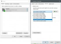
***EDIT: If listening on a Windows PC, you may want to be sure the shared sound output is set the the sample rate and bit-depth you want to play back, or Windows will perform real-time SRC on your audio stream making it sound worse than it should. I will post a screenshot below showing how Windows sound may be configured.
The headphone amp started out as one of these ebay cheapies: 1PCS LME49720NA+LME49600 headphone amplifier KIT | eBay which didn't sound that great given the weird power capacitor layout and low-ish feedback. I hacked mine by adding tantalum and ceramic decoupling caps at each IC, adding a copper tape foil ground plane, and mounting feedback and input resistors in the air above the PCB surface. Also, connected the LME49600 output pins in the air to avoid the long traces that ended up under my ground plane and also running next to the strange power distribution traces. The final circuit is the same as one of the LME40600 datasheet examples, with no stability problems, and pristine sound quality.
Addition of the headphone amp ends up making the completed project quite similar in sound quality to the Benchmark DAC-3 here, although without the number input options and remote control feature of the DAC-3.
I couldn't be happier with the result so far, but not quite done. Need some kind of unified power supply and case to put everything in. Also, still looking at adding USB input and maybe some other features. When it is done, I promised it to my son so he can have something good for mixing songs he is working on.
To change the subject a little for anyone perhaps interested in further modifications, all I did with my particular Chinese DAC was generally clean up the power, use recommended AVCC conditioning, use differentially summed IV circuits similar to ESS recommendations, and install an ultra-low-jitter clock oscillator module.
In addition to changes to the DAC board itself, the board is powered from one of Jan Didden's silent switcher +-15v supplies, there is an external LME49600 headphone amp, and also an external hardware SRC. One problem I found with the silent switcher is that it can pass some input noise to the output, so I supply it with clean +5v input power. Don't want to power it from an active USB hub.
The hardware SRC allows best performance with the slow-roll off minimum-phase reconstruction filter. If anyone wants to see what that sounds like there are some wav file examples here: DBX that have been software upsampled, or not. To me, the 24/96 upsampled CD rip sounds quite a bit better than the 16/44 version, especially with J3 installed on 1.06 version Chinese DAC to select the slow filter.
***EDIT: If listening on a Windows PC, you may want to be sure the shared sound output is set the the sample rate and bit-depth you want to play back, or Windows will perform real-time SRC on your audio stream making it sound worse than it should. I will post a screenshot below showing how Windows sound may be configured.
The headphone amp started out as one of these ebay cheapies: 1PCS LME49720NA+LME49600 headphone amplifier KIT | eBay which didn't sound that great given the weird power capacitor layout and low-ish feedback. I hacked mine by adding tantalum and ceramic decoupling caps at each IC, adding a copper tape foil ground plane, and mounting feedback and input resistors in the air above the PCB surface. Also, connected the LME49600 output pins in the air to avoid the long traces that ended up under my ground plane and also running next to the strange power distribution traces. The final circuit is the same as one of the LME40600 datasheet examples, with no stability problems, and pristine sound quality.
Addition of the headphone amp ends up making the completed project quite similar in sound quality to the Benchmark DAC-3 here, although without the number input options and remote control feature of the DAC-3.
I couldn't be happier with the result so far, but not quite done. Need some kind of unified power supply and case to put everything in. Also, still looking at adding USB input and maybe some other features. When it is done, I promised it to my son so he can have something good for mixing songs he is working on.
Attachments
Last edited:
Update & nice to know.
The ES9038 apparently doesn't like to push against a zero Ohm load, but prefers a bit of resistance. I first scanned from 0-500 Ohm with a pot meter, and everything larger than 30 Ohms or so made things worse, but below it, there was considerable improvement possible.
I went down from 10 Ohms to 2.7 (in series with both legs of the DAC output on one channel), and distortion continued to improve:
BY ALMOST 6 dB (above 200 Hz and as compared to a 0 Ohm load).
Then I soldered in 1.2 Ohm resistors to go even further down. However, when I wanted to measure the results, the board froze on me. Both DSD and Lock leds light up at the same time and that will be the end of this experiment.
Curious to find out if the same improvement can be made with the 9018 board in this way. That would really make it spectacular for the price.
- Home
- Source & Line
- Digital Line Level
- ES9038Q2M Board