Foghorn Leghorn!!!!!
From movie Superman (1978):
Did you ever CAREFULLY scan the page I linked to? It has an INTERACTIVE version of the d50s board image I posted. And it has a lotta info ... including the FACT that the D50 uses TWO 2qm Sabre chips (dual mono).
It's a SUPERB product at a SUPERB price. I'm gushin' .... I'm all outta adjectives.
SEEEEEUUUUPUHHHHHHBBBBBB!!!
Yeah, I have found pics from reviews before. However, I would like to know more than I can see in that pic. How about what are the frequencies printed on each clock? Where to the clock output pins go, directly to the dac chips, through something else? What exactly does the AVCC regulator design consist of? ...And so on.
If I had a board in front of me I could tell a lot more than looking at most of the pics I find. Also, with a board I could latch onto the I2C bus and watch the MCU program the dac registers, which can be pretty informative. All that having been said, a decent pic is better than having no pic")
From movie Superman (1978):
Lex Luthor : Some people can read War and Peace and come away thinking it's a simple adventure story. Others can read the ingredients on a chewing gum wrapper and unlock the secrets of the universe.
Did you ever CAREFULLY scan the page I linked to? It has an INTERACTIVE version of the d50s board image I posted. And it has a lotta info ... including the FACT that the D50 uses TWO 2qm Sabre chips (dual mono).
It's a SUPERB product at a SUPERB price. I'm gushin' .... I'm all outta adjectives.
SEEEEEUUUUPUHHHHHHBBBBBB!!!
I saw there were two dac chips, yeah.
What I want to know is whether or not the dac chips are being operated in asynchronous or synchronous mode for USB input?
I also would like to know, if its synchronous mode then are both clocks running all the time?
If so, how are the clocks switched to the dac chips?
And so on...
I know how Allo does theirs, which to my way of thinking is the right way, but the less common way.
Thing is, all dac manufacturers making dacs at, say, the $250 price point, have to make some decisions about how to allocate resources within budget. Is supporting SPDIF/TOSLINK/MQA more important than better clocking design for USB?
For me, I would prefer a sound I like more over having extra bells and whistles. Of course, if I need a certain feature then that would influence my choice too.
By the way, its good to hear you like D50. Given that its Topping, I assume the product is a good value for money. But, I think that's true for Allo as well.
Last edited:
In that link, what he calls listening test isn't a test. It's a subjective auditioning.Did you ever CAREFULLY scan the page I linked to?
i'm not surprised the d50 gets attention.
i have bought the d10s a bout a month ago, which is a stepped-down d50 in some way, and with a custom psu replacing the usb 5V, it is quite dynamic, though lacking detail/richness. But i'm only beginnig to mod. The psu i used is a tweaked sigma11, one of the best psu i ever heard. Only salas reg is more «natural sounding», but for the rest the sigma is right at the top, subjectively-speaking. i used those PSUS everywhere i can and where i can't afford the heat output of salas regs.
the main advantage of the D50 over d10s, i think, is that it uses lots of speperate regulators. in this case, i would speculate it uses multitude of 1117 regs, marked as l33d, but i may be wrong... Mine uses one l33d for dac chip and another for vref for output stage, but the rest of the LDOs are swithced mode, which is not optimal. the 1117, if my memory and experienced serve well, is a little noisy, but has very low Output impedance and the signature if quite pleasing, a bit like lm317. I have tried both in the past on another dac project.
i will replace clock with crystek, next and replace output stage buffer and the noisier SMPS....i think this dac has quite respectable potential. the sound signature is already not bad, and has respectable detail, as is. otherwise, with the stock usb power, it sounds average, like my average onboard computer audio.
Last edited:
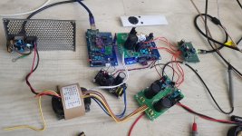
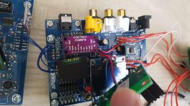
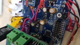
I be happy. A lot of job is finished! I'll replace ldo, not as a picture, for better looking. Everything is fooding of each ldo, with resistors on out. Replace all smd on good quality. I use opa1612. And in avcc opamp too opa 1612, not lm49720. Green board for i/v out and opamp for avcc was remake, now is lm317/lm337. in Ak4137 going 48khz resampling pcm. For es9038q2m signal is dsd 2.82mhz. i have remote control. And have many variables to join my DAC - opt, coax, Bluetooth 5.0 ldac, usb by amanero board with separate ldo. What will i need in future?!)
D50s for me is not interested, very small box. And need money for upgrade. And i'll pay a lot, that in this modification).
Sorry for my English)))
D50s for me is not interested, very small box. And need money for upgrade. And i'll pay a lot, that in this modification).
Sorry for my English)))
lm317 is still quite respectable for dac duties. not offensive for the ear at all. i like to give them hundreds of miliamps of bias current and put nichicon kz caps at output.
i have lme49720 in the d10s for buffer/se converter stage, but will try opa1622 and also salas dcg3 when parts arrive.
du you use opamps as simple regulator like in the flea ? PFM Flea regulator - group buy (cancelled, but do read the thread) | pink fish media
i'm curious about the opa1622 used as such!
i tried adm715X and was not super impressed, despite good resolution.
for me nothing beats sals and amb sigma11 for 5 volts (limit per design) and over.... for 3.3v, it's more complicated to find/build top notch regs.
Last edited:
lm317 is still quite respectable for dac duties. not offensive for the ear at all. i like to give them hundreds of miliamps of bias current and put nichicon kz caps at output.
i have lme49720 in the d10s for buffer/se converter stage, but will try opa1622 and also salas dcg3 when parts arrive.
du you use opamps as simple regulator like in the flea ? PFM Flea regulator - group buy (cancelled, but do read the thread) | pink fish media
i'm curious about the opa1622 used as such!
i tried adm715X and was not super impressed, despite good resolution.
for me nothing beats sals and amb sigma11 for 5 volts (limit per design) and over.... for 3.3v, it's more complicated to find/build top notch regs.
I use opamp for avcc in post 3003. This is talking Mark
What will you say about opa2604?opa1622 may be better than opa16212 for a simple opamp regulator. It has (much) lower output impedance in the audio band, and higher current cappability, and is specified for a (tiny) bit lower supply voltage.
Hi 888777,
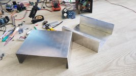
Looks like you are having some fun there. Good for you!
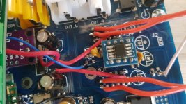
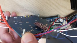
One thing I did notice is that some of your solder joints look overheated. I couldn't tell if your solder iron has a temperature control? Also, that little sponge that sits at the bottom of the solder iron holder is supposed to be wet with water. Then it will clean the iron's tip much, much better. If you don't want to use a wet sponge, you can use soap-less dry brass pot scrubbing pads or a commercial version such as: HAKKO | Tip Cleaner / Iron Holder | HAKKO 599B
Then of course, always use clean rosin-core solder (or other low temperature electronics solder with flux). If your solder wire is oxidized, you can try wiping with a paper towel or similar until the dark oxidation stops coming off.
Then, strip wires, twist the strands together, and then 'tin' the wire by applying a nice shiny coat of solder to the wire before trying to solder it to anything else.
Cut off any extra length of tinned wire and try to not use any more solder iron temperature than you need. If the iron is too hot it will burn out the flux too fast and the wire insulation with melt back.
My only point is that its worth it to take the time and effort to solder like a professional. It will help you later when you need the skill to do more challenging projects.
Best,
Mark
Looks like you are having some fun there. Good for you!
One thing I did notice is that some of your solder joints look overheated. I couldn't tell if your solder iron has a temperature control? Also, that little sponge that sits at the bottom of the solder iron holder is supposed to be wet with water. Then it will clean the iron's tip much, much better. If you don't want to use a wet sponge, you can use soap-less dry brass pot scrubbing pads or a commercial version such as: HAKKO | Tip Cleaner / Iron Holder | HAKKO 599B
Then of course, always use clean rosin-core solder (or other low temperature electronics solder with flux). If your solder wire is oxidized, you can try wiping with a paper towel or similar until the dark oxidation stops coming off.
Then, strip wires, twist the strands together, and then 'tin' the wire by applying a nice shiny coat of solder to the wire before trying to solder it to anything else.
Cut off any extra length of tinned wire and try to not use any more solder iron temperature than you need. If the iron is too hot it will burn out the flux too fast and the wire insulation with melt back.
My only point is that its worth it to take the time and effort to solder like a professional. It will help you later when you need the skill to do more challenging projects.
Best,
Mark
Guys,
The problem with OPA1622 is that it is 10-pin device. It has a ground pin that is supposed to be connected to real ground. OPA1622 on an 8-pin DIP adapter is not good. It sorta works, but distortion is higher than it would be with the ground pin properly grounded. Also, its really more of low power, ultra-low distortion headphone amp, its not as good for most dac purposes as OPA1612. It may help to know that both ESS and AKM use OPA1612 on their current-output-dac-chip evaluation boards (all of ESS dac chips, and AK4499).
The problem with OPA1622 is that it is 10-pin device. It has a ground pin that is supposed to be connected to real ground. OPA1622 on an 8-pin DIP adapter is not good. It sorta works, but distortion is higher than it would be with the ground pin properly grounded. Also, its really more of low power, ultra-low distortion headphone amp, its not as good for most dac purposes as OPA1612. It may help to know that both ESS and AKM use OPA1612 on their current-output-dac-chip evaluation boards (all of ESS dac chips, and AK4499).
Thanks, Mark.Hi 888777,
Looks like you are having some fun there. Good for you!
One thing I did notice is that some of your solder joints look overheated. I couldn't tell if your solder iron has a temperature control? Also, that little sponge that sits at the bottom of the solder iron holder is supposed to be wet with water. Then it will clean the iron's tip much, much better. If you don't want to use a wet sponge, you can use soap-less dry brass pot scrubbing pads or a commercial version such as: HAKKO | Tip Cleaner / Iron Holder | HAKKO 599B
Then of course, always use clean rosin-core solder (or other low temperature electronics solder with flux). If your solder wire is oxidized, you can try wiping with a paper towel or similar until the dark oxidation stops coming off.
Then, strip wires, twist the strands together, and then 'tin' the wire by applying a nice shiny coat of solder to the wire before trying to solder it to anything else.
Cut off any extra length of tinned wire and try to not use any more solder iron temperature than you need. If the iron is too hot it will burn out the flux too fast and the wire insulation with melt back.
My only point is that its worth it to take the time and effort to solder like a professional. It will help you later when you need the skill to do more challenging projects.
Best,
Mark
I have regulatot of temperature, now 350°C. I'll remake wires and replace a lot of ldo for better looking, and get your message in my attention)
Last edited:
- Home
- Source & Line
- Digital Line Level
- ES9038Q2M Board