Idir I would be interested in a balanced pcb, but I would assume most people would be happy with unbalenced. I think a lot of people would like one too ") I see 2 ways of placing it: 1. Place the pcb at the opamp side of the dac board. People don't use the round power plug anyway. The new opamp pcb could have ground plane going up to the top layer trough a lot of vias and be soldered to the original ground plane. That is the most used method here I think..
I see 2 ways of placing it: 1. Place the pcb at the opamp side of the dac board. People don't use the round power plug anyway. The new opamp pcb could have ground plane going up to the top layer trough a lot of vias and be soldered to the original ground plane. That is the most used method here I think..
2. Or assume people would remove the old op amp system and the new pcb could be layed flat on top and using the existing op amp pin holes as vias connecting the ground planes. The audio wires from the dac would be very short and the whole thing would be very compact, especially with smds.
I see 2 ways of placing it: 1. Place the pcb at the opamp side of the dac board. People don't use the round power plug anyway. The new opamp pcb could have ground plane going up to the top layer trough a lot of vias and be soldered to the original ground plane. That is the most used method here I think..2. Or assume people would remove the old op amp system and the new pcb could be layed flat on top and using the existing op amp pin holes as vias connecting the ground planes. The audio wires from the dac would be very short and the whole thing would be very compact, especially with smds.
Better to avoid vias if possible. Maybe better to use copper foil to connect ground planes in a wide strip. Have to think about what that might effect other ground currents in the attachment area, etc.
Regarding balanced outputs, there is only one proper way to do that and it is the way Benchmark did it in DAC-3. Take a filtered and processed unbalanced output and rebalance it with two opamps (one dual opamp per channel).
Regarding balanced outputs, there is only one proper way to do that and it is the way Benchmark did it in DAC-3. Take a filtered and processed unbalanced output and rebalance it with two opamps (one dual opamp per channel).
Regarding balanced outputs, there is only one proper way to do that ...
Probably, it would have been more correct to say the best way to make balanced dac outputs that are low distortion and low cost uses opamps. Transformers can also be used to convert unbalanced outputs to balanced, although good ones tend to be expensive, and they are likely to produce more distortion than a good opamp circuit would.
I plan to use Mr.Slim schematic on page 301, is that what you mean Mark? When using the Rasberry board and Volumio, I assume we have to hardwire a switch for those 2 buffers(pins) to swap between Volumio and the other inputs on the board? I assume the display and remote dosn't work while using the Volumio since the onboard control chip is deactivated?
I plan to use Mr.Slim schematic on page 301, is that what you mean Mark? When using the Rasberry board and Volumio, I assume we have to hardwire a switch for those 2 buffers(pins) to swap between Volumio and the other inputs on the board? I assume the display and remote dosn't work while using the Volumio since the onboard control chip is deactivated?
If you look at the next post after MrSlim's with the schematics, regarding unbalanced outputs, you see my reaction to seeing those for the first time. Actually, what I said at first was a little different, but I edited it to make it more nice sounding. I have to disagree with taking unbalanced outputs from the I/V stages, as we haven't finished with the proper filtering. Let's do it right, then make it balanced after that, if needed.
Regarding the I2C bus signals, SDA and SCL, there can only be one I2C master, in most cases. (It requires special software/firmware design to use more than one master.) That means that when J1, J2 are installed on the dac board to halt I2C bus activity by the MCU, then the bus is free so RPi can take over as master. During that time the display is not going to be able to work. I guess maybe you could write an RPi program to control the display, but probably not worth the bother.
Anyway, since with v1.07 dac firmware, installing J1, J2 halts the dac MCU, there is no need for a switch. If you can't get the MCU to stop using the I2C bus, like what happened to me with my 1.07 board, then you need to do pin lifting of the MCU, or trace cutting, one way or another. You could then use a switch, but I use a relay controlled by Arduino.
Last edited:
I plan to use Mr.Slim schematic on page 301, is that what you mean Mark? When using the Rasberry board and Volumio, I assume we have to hardwire a switch for those 2 buffers(pins) to swap between Volumio and the other inputs on the board? I assume the display and remote dosn't work while using the Volumio since the onboard control chip is deactivated?
hi, there,
if follow my instructions, settings and playback information are on the volumio ui including the hw-vol, we don't need the display or ir remote.
the fir filters are awkward, if we change from the k2m plugin, we get:
fast roll = linear phase fast roll-off
slow roll = linear phase slow roll-off
minimum phase = minimum phase fast roll-off
but any playback, pause or hw-vol operations will bring it back to default apodizing fast roll-off.
we can experiment that 3 accessible filters by matching the playback and plugin volumes, start play a soundtrack then change the filter. at the end of the track or any new operation it will back to default.
i'm working on the plugin to get all 7 filters operative, until the new releasing enjoy the music.
cheers
Last edited:
I have to disagree with taking unbalanced outputs from the I/V stages, as we haven't finished with the proper filtering. Let's do it right, then make it balanced after that, if needed.
Is it OK if I follow MrSLIM's chematic and just delete balanced outputs and use unbalanced, that are also there?
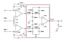
Yes. MrSlim's schematic is correct from my perspective aside from the addition of the unbalanced outputs. So, I would just say print it out and put some White-Out on the unbalanced outputs. With that in mind, it is the schematic I recommend to use when building an output stage from the instructions I wrote up.
If it helps, I can post a copy of the output stage schematic I used. It was the source that bih and later MrSlim originally started with.
If it helps, I can post a copy of the output stage schematic I used. It was the source that bih and later MrSlim originally started with.
Attachments
Last edited:
Hi Paul,
Guess I should have edited the schematic before now. It does look like it might be a little easier for builders to read.
Good to hear of your plans to get started.
Please let us know if any problems or questions. Don't forget the output stage sound quality may be improved with film caps added to the +-15v rails. I haven't tried to figure out the minimum amount that works best (which may vary with type of +-15v supply used), but tested with about 100uf per +-15v rail.
Also, we always like to look at pictures of builds. Be great if you get a chance to take some along the way.
Mark
Hi Mark,
Thanks for the tips. I finally ordered the parts from Mouser. Though it might take a while to reach me. I also include parts for a lt3032 low noise regulator for the +-15 volts, as on the datasheet pictured here: lt3032-15dual — imgbb.com
The regulator is rated for 150ma. I am hoping it will be enough to run the 4 opamps. I plan to drive it with adjustable lm317/337.
I also ordered an array of smd prototype boards from aliexpress as suggested.
Another question if I may:
I have the blue board. Since most of the mods will supply separate power to critical components, do I need to mod the 12v power to +-15v as shown in previous post by cutting traces on the board?
Cheers,
Kay
Hi Kay,
Interesting you want to use LT3032. 150mA might not be enough for the three output stage opamps and the AVCC opamp, at least it might very close to the limit. I see they have pads under the bottom of the chip that are supposed to be soldered down to the PCB to help with heat dissipation. Wouldn't be surprised if you have some trouble with that, but you may find you can get by with only LM317/LM337 and some film caps. It can help to use ultra-soft recovery rectifier diodes for the power supply too. Typical 1N400x type diodes have can interact with the power transformer to produce a lot of high frequency ringing when transformer windings are commuted off. Soft recovery diodes can help a lot to prevent that as can carefully chosen RC snubber components. Otherwise, high frequency ringing can get into circuitry and cause diminished sound quality.
In case you may be interested to know, I use one of these for +-15v: Ultra-low Noise +/- Adjustable Voltage Regulator Module, LT1963A LT3015. x 1PCS | eBay
Also, use one of these for dac board +5v and for AK4137 board:
Low Noise LT3042 Linear Regulator Power Supply Board DC Converter Overvoltage | eBay
Regarding the blue board, it depends. If you find the correct post with pictures, yes, normally you would cut a trace that connects the -15v rail to ground. However, that assumes you intend to use the +-15 volt terminal pads on the dac board at all. I don't use them with my 2nd modded dac. The +-15 power comes into terminals on the output stage board, and +5v for the low voltage dac supplies and for LTC6655 comes from an external +5v supply. So, there is no need for any of the +-15v power traces, nor for +15v input power to the +5v or +8v linear regulator that is there to provide input power for the 3.3v AMS1117 regulator. Please let me know if further clarification could be useful.
Best of luck with your project, and hope things turn out well. As always, any pictures of your project would be of interest to the group, and particularly so for other folks considering starting on a project of their own.
Please do not hesitate to ask any questions that may come up along the way.
Cheers,
Mark
Interesting you want to use LT3032. 150mA might not be enough for the three output stage opamps and the AVCC opamp, at least it might very close to the limit. I see they have pads under the bottom of the chip that are supposed to be soldered down to the PCB to help with heat dissipation. Wouldn't be surprised if you have some trouble with that, but you may find you can get by with only LM317/LM337 and some film caps. It can help to use ultra-soft recovery rectifier diodes for the power supply too. Typical 1N400x type diodes have can interact with the power transformer to produce a lot of high frequency ringing when transformer windings are commuted off. Soft recovery diodes can help a lot to prevent that as can carefully chosen RC snubber components. Otherwise, high frequency ringing can get into circuitry and cause diminished sound quality.
In case you may be interested to know, I use one of these for +-15v: Ultra-low Noise +/- Adjustable Voltage Regulator Module, LT1963A LT3015. x 1PCS | eBay
Also, use one of these for dac board +5v and for AK4137 board:
Low Noise LT3042 Linear Regulator Power Supply Board DC Converter Overvoltage | eBay
Regarding the blue board, it depends. If you find the correct post with pictures, yes, normally you would cut a trace that connects the -15v rail to ground. However, that assumes you intend to use the +-15 volt terminal pads on the dac board at all. I don't use them with my 2nd modded dac. The +-15 power comes into terminals on the output stage board, and +5v for the low voltage dac supplies and for LTC6655 comes from an external +5v supply. So, there is no need for any of the +-15v power traces, nor for +15v input power to the +5v or +8v linear regulator that is there to provide input power for the 3.3v AMS1117 regulator. Please let me know if further clarification could be useful.
Best of luck with your project, and hope things turn out well.
As always, any pictures of your project would be of interest to the group, and particularly so for other folks considering starting on a project of their own. Please do not hesitate to ask any questions that may come up along the way.
Cheers,
Mark
Last edited:
Mark,
Regarding the LM317/337, the one I ordered locally supply seems to be luckily on point with what you're saying, quote, "The kit uses state-of-the-art soft-recovery power rectifier diodes that reduce the diode ringing thus reducing the noise.The kit also uses a dual bridge rectifier configuration and isolates the AC center tap from the ground and thus eliminating the chance of hum / noise." Octave 1 - LM317-337CRCPSU - High Quality Dual Adjustable CRC Regulated Power Supply
Hope it will do. Or else I can add film caps as suggested.
Kay
Thanks for the heads up. I'd have to leave it for another project.LT3032. 150mA might not be enough
Regarding the LM317/337, the one I ordered locally supply seems to be luckily on point with what you're saying, quote, "The kit uses state-of-the-art soft-recovery power rectifier diodes that reduce the diode ringing thus reducing the noise.The kit also uses a dual bridge rectifier configuration and isolates the AC center tap from the ground and thus eliminating the chance of hum / noise." Octave 1 - LM317-337CRCPSU - High Quality Dual Adjustable CRC Regulated Power Supply
Hope it will do. Or else I can add film caps as suggested.
Did you use yours directly after the transformer secondary or after lm317/337?I use one of these for +-15v
I already have the lt3042 5v & 12v.Also, use one of these for dac board +5v
I did wonder looking at your pictures that you lifted the pin of this regulator. Does that mean lt3042 5v feed directly into this regulator pin?provide input power for the 3.3v AMS1117 regulator
Kay
Hi Kay,
The LM317/LM337 board you selected looks fine. Almost certainly, you will find you get better sound quality with 100uf of film caps connected from +15v to ground, and another 100uf from -15v to ground ('ground' meaning the green power supply output common wire which only connects the dac board ground plane. We don't want to create any unnecessary ground loops with extra connections to earth or the chassis). The caps should be located close to where +-15v power enters the dac board.
Don't think you should need both +5v and +12v? Only use +5v here. You are correct that I lifted the output pin of the stock +5v regulator in order to disable it. I soldered a red wire to the existing filter cap on the dac board where the +5v regulator pin was lifted to create a new entry point for +5v. That wire connects to the LT3042 w/pass transistor board + output. The - output from the LT3042 supply connects to the dac board ground plane a little bit down closer to the dac chip end of the dac board, using a black wire.
Mark
Last edited:
- Home
- Source & Line
- Digital Line Level
- ES9038Q2M Board