Greetings. I wish to create an IV stage for a parallel TDA1541 dac. The d3a tube with an OPT seems the best option to me (I like transformers more than caps in the signal path). I would of course like to have low output impedance and output about 2V.
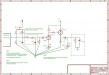
But I am not a real tube designer so I have drawn a schedule (based on various sources) but have some questions about it (orange):
1. Is the 20 ohm the correct value to load the 2 times TDA1541's?
2. Is the 100 ohm value correct?
3. What will be the gain with the OPT 2:1 step-down versus 3:1 step-down? Also the output impedance?
4. Do I miss anything that might be beneficial for this circuit?
5. Did I do anything stupid?
Thanks 🙂
Attachments
I have similar configuration but only with one TDA1541 per channel.
I'm using 33R as I/V resistor. Theoretically the value should be somewhere between 22 and 68 ohm.
Instead of 100 R cathode resistor and cap you can try LED diode.
I'm using 33R as I/V resistor. Theoretically the value should be somewhere between 22 and 68 ohm.
Instead of 100 R cathode resistor and cap you can try LED diode.
Last edited:
Hi,
maybe these links will help you:
Hi-end Balanced Circlotron Hybrid Amplifier
http://www.kandkaudio.com/images/Input Stage for 2 Stage PP Amp.pdf
maybe these links will help you:
Hi-end Balanced Circlotron Hybrid Amplifier
http://www.kandkaudio.com/images/Input Stage for 2 Stage PP Amp.pdf
The 20 ohm Riv might be too big value for the TDA1541A because of the 25mV
recommended off-set by the data-sheets. Any larger value will increase distortion.
So the value of Riv = (2 x offset [V]) / Abs(Iout)[A], Riv = 2 x 0.025V / 0.004mA = 12.5 ohm. That is for ONE chip. For 2 it will be 1/2, 6.25 ohm or 1st lower value. Essentially NON inductive part. And mounted closer to the gain stage than Dac chip...
.
But You should apply Current injection at output of about 1/2 Abs(Iout)[A],
that is 2mA. It could be simple JFET current source adjusted to 2mA. Close to each Io pin.
.
After that for 2V out You will need about 40 times gain stage...
.
In Your case the interstage transformer should be from very high quality to acheive good bandwidth. That is mainly covered by the internal resistance of the tube, and primary inductance of the trafo, capacitances of the trafo.
.
Take a look into the datashhet of the D3a, in range of about 20mA it have little bit higher than 2Kohm internal resistance. That desreves much primary inductance for low end range. maybe close to the 3 digit first value... While the amplification factor is about 80 times, so the step down trafo if used, it should be 2 : 1. Put some 100ohm resistor to G2 🙂
cheers
Last edited:
Thanks all!
Hi Zoran do you have an example of "current injection". Why would I need this? I am trying to keep the circuit a simple as possible. But if needed I will add it.
Hi Neskor for the led/diode for which voltage between earth and pin 1 should I aim? I have an Ultrapath pre-amp (ElectraPrint circuit) where I also use diodes. Sounds indeed better than the resistor.
Indeed I am going to use a high quality OPT from a respected small company in the Netherlands. In the end I will use this dac to connect to a computer drive and I will build the whole in 2 cases. One for all power circuits (computer, harddisk, usb receiver, dac, heater, tube) and one for the computer drive (mini-itx) with dac/tube circuit. And I will need a ipad for the computer operations.
Trying to clean up my hifi cases clutter (will reduce 5-6 boxes into 2) and power cable needs (from 5 power cables to 1). Will take me some months though. Will also have to wait for the transformers being build.
Last edited:
It is hard to obtain +15 when tube output used. +15 and -15V are present when OP or JFET or BJT stage are at the output of DAC... But You could use the same example with +5V
power supply already present as TDA1541A power... It is not Analog line but for the try will no harm the chip or other devices. BUT first adjust the 2mA current without connect to chip. After adjusting 2mA value (measure), then connect to the chip and measure again optionally readjust. Measure from +5V to JFET. 🙂
power supply already present as TDA1541A power... It is not Analog line but for the try will no harm the chip or other devices. BUT first adjust the 2mA current without connect to chip. After adjusting 2mA value (measure), then connect to the chip and measure again optionally readjust. Measure from +5V to JFET. 🙂
Thanks I need to really study this current injection topic which I will do! Also I am assured that this is a doable project for me so I will proceed.
I think neskor and Zoran mean to nullify the voltage output at (I out) ??
I have boards with a trimpot which divides the power supply voltage +/-15V rails and is connected to the I out. I adjust this dc. source with trimpot until there is 0V = (I out) to ground.
I have boards with a trimpot which divides the power supply voltage +/-15V rails and is connected to the I out. I adjust this dc. source with trimpot until there is 0V = (I out) to ground.
Hi, I'm using TDA1541A over 20 years with passive I/V and experimented a lot with output stages. My final set up is: 22 Ohm I/V resistor, stepup transformer (x16), tube stage (Lampizator with mini tubes), step down transformer (Sowter 9150) to reduce output impedance.
@JEV: I think you do not have enough gain with only 1 tube stage! Especially not because you want to step down 2:1
@JEV: Great idea to use step down transformer! You need it to reduce the load of the next (pre)amplifier, unless this is a tube amplifier with >100k ohm input impedance. A step down transformer will also transform load impedance from the secondary to primary by square.
By example: step down output voltage 2:1 results in 2x2=4 times higher load impedance for your D3a tube. So a 20 kohm input impedance of the next amplifer stage (after the D3a) results in a load of 4x20=80 kohm for the D3a. It is my experience that the tube (your D3a) shall be loaded as minimum as possible to really shine!
Hi Richard. I was looking at the Sowter dac transformers. is that he one you use? If so which type?
About the gain. I will use 2 dac chips in parallel and the D3a does x70 in 1 stage.
Did you ever study the topic of the "current injection"?
About the gain. I will use 2 dac chips in parallel and the D3a does x70 in 1 stage.
Did you ever study the topic of the "current injection"?
Hi Jev, The step-up is a handmade type over 20 years ago by a professional in the Netherlands (Tribute). The step-down is Sowter 9150 type which can step down in 4 steps each -10 dB.
For me the Sowter is also the (passive) pre-amp stage for rough volume control. I always use my laptop for playing music over Youtube and Spotify and use their volume functions for fine volume. Works great and no active pre-amp anymore needed.
OK 70x! Not bad for a tube . If you use the Sowter with -10dB step down your amplification will be 70/3=23x. Could work.
No, I was not aware of the current injection. Will have a look into it. Thx Neskar for publishing (Dobre)
Find enclosd my schematic, may be helps for understanding.
For me the Sowter is also the (passive) pre-amp stage for rough volume control. I always use my laptop for playing music over Youtube and Spotify and use their volume functions for fine volume. Works great and no active pre-amp anymore needed.
OK 70x! Not bad for a tube
. If you use the Sowter with -10dB step down your amplification will be 70/3=23x. Could work.No, I was not aware of the current injection. Will have a look into it. Thx Neskar for publishing (Dobre)
Find enclosd my schematic, may be helps for understanding.
Attachments
Last edited:
I am reading this thread and I want to comment. I read the document written by Pedja and there is no current injection. The output I out consist of a -0 to -4 mA a.c. signal and there is an average -2 mA current at the output which is bad for the opamps bias. In the opamps or discrete transistors that - 2 mA signal current bias can bias the input stage wrong. In tube amps you can deal with this or ignore it. What pedja's is saying is that if you create a voltage potential and you raise the signal to let say 3 to - 1 mA this will affect the DAC internal functioning, as this is referenced over 0 mA of average output current the dac output will receive a positive voltage in its output stage. I experimented with this and transistors will sound better with a null reference at input and I think the dac likes to see some voltage at the output. In tubes there is no need to do this. Also the lampizator schematic has not worked well for me resulting in excessive distortion and amplification. A simple passive resistor followed with a one tube cathode follower is what sounded best with tubes and I also built a headphone amplifier straight from it. However, with transistors and feedback there is much more resolution and it fully retains the details and musical texture of this unique dac.
Last edited:
@gabdx. Thx for your comment and explanation. I didn't read the Pedja document yet but your explanation seems logical. This is also the reason to limit the I/V resistor to ~22 Ohm (for 1 DAC output).
As you will see in my schematic I use step-up transformer after I/V resistor which eliminates any DC effect. I experimented with several tube output stages but for me the SRPP mini-tubes design of Lampizator works very fine and up till now the best sounding result. I also use them in a pre-amp design. No idea why you had problems with them.
This design has been reviewed by an independant person running an exclusive high-end shop and compared with expensive DAC's form Antilope and Wadia but became the clear winner. So it can work!
Hi Richard, thanks for sharing the schema. I hope to be using a Tribute output transformer for this project.
@gabdx thanks for responsing. But I will pursue the tube option 🙂 I like the tube sound better (use a Weiss dac202 now which is great BTW).
What I understood from info of other projects is that a DC offset can saturate the primary side of the transformer and thus prevent it from being efficient especially in the bass regions. In my project I will experiment with this (will take several months still I expect.)
See the solution from First DIY DAC, Using TDA1541A (part arond Q1).
Attachments
Last edited:
Hi Jej, your right that the 2 mA current drawn by the dac output can saturate very small transformer magnetic core and degrade quality.
Remember that many transformer designers will build their transformer with this in mind: Sowter designs for 0.6 mA his dac output transformers. Could be easy for him to raise this to 2mA and maybe you get the best tda1541
I could build you boards with transistors and you provide the 30vdc supply 🙂 I will send to you by mail.
Last edited:
Update, the thing is playing music. Some weird distortion in the right channel. Need to sort that out and may be tidy it up a bit. Also make a wooden case. Very glad it works 🙂
http://www.diyaudio.com/forums/attachment.php?attachmentid=476620&stc=1&d=1428599239
http://www.diyaudio.com/forums/attachment.php?attachmentid=476621&stc=1&d=1428599239
http://www.diyaudio.com/forums/attachment.php?attachmentid=476620&stc=1&d=1428599239
http://www.diyaudio.com/forums/attachment.php?attachmentid=476621&stc=1&d=1428599239
Attachments
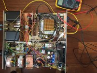
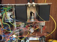
Hi jev, it is a great construction!
What is the circuit? where is the tda1541 ??? did you have the transformer for balanced outputs?
If you have 30vct supply I can send you a completed feedback transistors board for evaluation, and you send it back after a few months. I am curious how you would compare to your super nice circuit. This has a lot of potential
- Status
- Not open for further replies.
- Home
- Source & Line
- Digital Line Level
- D3a IV stage