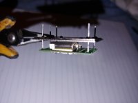
I recently finished my oven build. But I dont think it's working properly.
When powered with 16v dc on my benchtop PSU. The oven board is drawing 0.5A at 16V.
R1 alone takes 5V, and getting hot very quickly.
I turned it off after that, fear it's going to damage the board. Both of my boards are behaving the same, and all passive components have the correct values.
What would the problem be? or I should leave it running to stabilize?
I recently finished my oven build. But I dont think it's working properly.
When powered with 16v dc on my benchtop PSU. The oven board is drawing 0.5A at 16V.
R1 alone takes 5V, and getting hot very quickly.
I turned it off after that, fear it's going to damage the board. Both of my boards are behaving the same, and all passive components have the correct values.
What would the problem be? or I should leave it running to stabilize?
This is normal. The parts on oven board will reach 90+ celsius easily. In my case the current consumption will gradually decrease to 200ma.
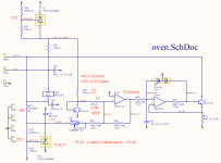
I have made an oven circuit as an option for something completely different
(keeping some FETs at 40°C). It is therefore a snippet from some larger circuit
and not of prime importance to me, but it seems to work.
Last summer there was a discussion about it in the LTspice users list,
including simulation.
The only hot parts are a BD140 used as a sensor and a BD139 used as heater.
I was surprised how fast the heat travels through the alu block.
Sorry, no boards or further interest from my side, but easy on perf board
if someone wants to play.
xxx on parts values means that the original part has been edited and should
be re-imported from the library with correct value to get a clean BOM.
cheers, Gerhard
Attachments
Last edited:
I doubt that's my case, under 30 seconds running, you can clearly see my R1 cooking.This is normal. The parts on oven board will reach 90+ celsius easily. In my case the current consumption will gradually decrease to 200ma.

Also R1 is rated for 3W. With .5A running through it, it's working way over it's rating.
I doubt that's my case, under 30 seconds running, you can clearly see my R1 cooking.
Also R1 is rated for 3W. With .5A running through it, it's working way over it's rating.
R1=10R, I=0.5, W = I^(2) x R, 0.5^(2)*10=2.5W
It's still under 3W at start up. However, my R2 fried once after 1 or 2 yrs of non-stop operation.
Last edited:
I doubt that's my case, under 30 seconds running, you can clearly see my R1 cooking.
Also R1 is rated for 3W. With .5A running through it, it's working way over it's rating.
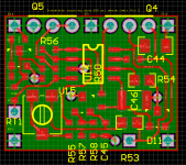
The method of heat transfer from those SMT resistors to the copper shell is
sub optimal. The resistors will transfer most of their heat to the PCB and a
very small amount to the copper. Once it is transferred to the copper it then
has an inefficient path to the crystal can - which is where you want it.
There are many many options, I suggested one here:
https://www.diyaudio.com/forums/dig...jitter-crystal-oscillator-54.html#post4283862
- Another option is to use 2 off, very thin / small size Rogers or Aluminium
PCB's with the SMT resistors mounted directly. These 2 boards can be
clamped to the crystal can with 1 or 2 a Nitrile O rings. Heat transfer straight
through PCB to can.
TCD

X7R aging
Have one to choose C1 in automotives parts catalog because the close hot oven ?
Btw how the X7R and non class 1 caps aging affect the oscillator perf, please? Does the micro bonding of class II ceramic can affect the crystal perf on a same pcb or natural vibration of the cabinet are far more important ?
Sorry for this, I'm totally noob here.
No. From the photo in #2007 it is just the input capacitor of the 7812, needed
to prevent the regulator from oscillating or other misbehaving in case of large
ps impedance. Half or twice the value makes probably not the slightest difference.
I think the 78xx data sheet requires it and the values can be checked there.
As long as the regulator does not go hiwire the capacitor has no influence on anything.
I have no idea about R1. If you make it smaller, the 7812 probably will have to
burn R1's share, too.
FWIW HP used transistors as the heaters in the 10811 OXCO and those have worked well for a long time. it may simplify the overall circuit. The manual with many details is available online. Manuals - KO4BB
Its from back when you could learn something from the manual.
Its from back when you could learn something from the manual.
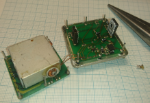
That is actually common practice. Where else do you get a tab with a
bolting hole for easy thermal coupling and the control input in one piece?
I have just opened a Morion MV89A that ceased oscillating with most
Vtune voltages, so I can at least recover the 5.000 MHz SC overtone
crystal for own experiments.
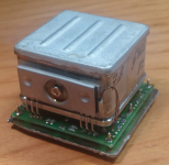
The box is the inner oven. It has 4 transistors for smooth heat transfer.
There is another fat transistor below the box on the board that seems
to be thermally coupled to the bottom plate of the outer case.
Apart from more uniform heat distribution, sharing the thermal load
between 4 transistors decreases their junction temperature.
It was actually not very hard to open the outer oven. Once I had
filed away a bottom corner I could prune away the cover. It was soldered
but the tin does not bond too firmly to the steel.
Next weekend I'll open the inner oven.
bolting hole for easy thermal coupling and the control input in one piece?
I have just opened a Morion MV89A that ceased oscillating with most
Vtune voltages, so I can at least recover the 5.000 MHz SC overtone
crystal for own experiments.
The box is the inner oven. It has 4 transistors for smooth heat transfer.
There is another fat transistor below the box on the board that seems
to be thermally coupled to the bottom plate of the outer case.
Apart from more uniform heat distribution, sharing the thermal load
between 4 transistors decreases their junction temperature.
It was actually not very hard to open the outer oven. Once I had
filed away a bottom corner I could prune away the cover. It was soldered
but the tin does not bond too firmly to the steel.
Next weekend I'll open the inner oven.
Attachments
Last edited:
Yes, that is some PTC ceramic, usually for 40°C but not very precise.
I think it used to be available here already 30 years ago for ham radio:
< Quarze + Quarzheizer - Kuhne electronic Shop >
but I see that they have now a small smd board.
The crystals they sell are mostly for their own kits, I don't think that
they are a potential source for audio xtals. No production of their own.
Yes, that is some PTC ceramic, usually for 40°C but not very precise.
I think it used to be available here already 30 years ago for ham radio:
Looking around net, many OCXO's use this technique. That particular batch
of OCXO's were not hugely consistent WRT their Allan Dev specs, so maybe
the heater has some impact on this, not sure.
One thing in favor of the copper shroud Andrea has used is the thermal
mass.
TCD
New Driscoll at 22.5792MHz
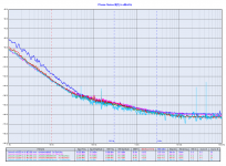
I attach the phase noise plot of the new Driscoll oscillator that implements the Laptech 3rd overtone SC-Cut crystal at 22.5792 MHz at different drive levels.
The plot of the SC-Cut 11.2896 MHz crystal coming soon.
I attach the phase noise plot of the new Driscoll oscillator that implements the Laptech 3rd overtone SC-Cut crystal at 22.5792 MHz at different drive levels.
The plot of the SC-Cut 11.2896 MHz crystal coming soon.
Attachments
Nice. ")
In
< Phase Noise and Frequency Stability in Oscillators The Cambridge RF and Microwave Engineering Series: Amazon.de: Enrico Rubiola: Fremdsprachige Bucher >
there is a chapter for interpreting these plots, including speculations on XTAL Q
and drive level.
WOW. €2300 for the hard cover. No wonder thet J.B. can donate 10 billions.
All traces but the dark blue one could be easily interpreted. What was different there?
it really seems to be 1/f**4 instead 1/f**3.
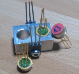
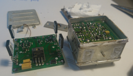
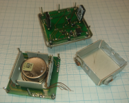
I have continued with the crystal recovery from #2013.
The outer box is not the box of the outer oven. The outer oven is
what's inside. What I identified as the outer heater transistor is
only a 10V regulator.
The outer box is not the box of the outer oven. The outer oven is
what's inside. What I identified as the outer heater transistor is
only a 10V regulator.
Attachments
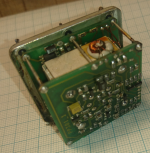
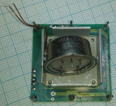
Now the inner oven. It is only plugged together, not soldered.
The coils probably belong to the 5 -> 10 MHz doubler.
Next thing is to measure the crystal parameters.
The crystal analyzer program of the DG8SAQ VNWA did not give
conclusive results.
The coils probably belong to the 5 -> 10 MHz doubler.
Next thing is to measure the crystal parameters.
The crystal analyzer program of the DG8SAQ VNWA did not give
conclusive results.
Attachments
Last edited:
- Status
- Not open for further replies.
- Home
- Source & Line
- Digital Line Level
- The Well Tempered Master Clock - Building a low phase noise/jitter crystal oscillator