Hi,
Any mistakes would be that of the designer.
You need to understand that.
He is not open to suggestion = correction. "I take it all in my stride" and never answer simple question like 'what about galvanic isolation', 'why for the cap between supply lines -15 to -5 and +5v'.
ala Eldam comment to him "all is under control"
You need to understand that this is not a group project.
That is my point.
Check the forum, check the track record.
You give, he take… and then sell it back.
Still, missing the major points of the original "any good 1541A kit" thread.
Amazing (not really)_
So, in the end.. go milk a duck.
Sun
After some distance you in my mind are correct.
Sorry to have come here and peace to you and yours.
1541A thread this one is no good.
Doce
After some distance you in my mind are correct.
Sorry to have come here and peace to you and yours.
1541A thread this one is no good.
Doce
They say that the fish rots firstly from the head.
In this case, the whole fish was rotten to begin withs.
Sun
Andrea,
Attached is the impedance plot for all 3 supplies vs impedance, appreciate your time.
Cheers.
Hi Ryan,
can you expand the plot up to 100 MHz?
Andrea
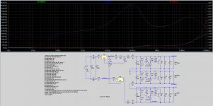
100 meg phase plot
Hi Andrea,
Attached is the phase plot up to 100Meg, but i've changed a few things since the last plot.
C13, C15, C1 - changed to 40 mohm ESR. (10 mohm before)
C21, C22, C12 - reduced to 1nF and set to 6 mohm ESR, and the ESL is at 400pH.
C8, C11, C20 - removed/set to 0 for now.
After 100Meg things get a little pear shaped again. I couldn't find an exact value for the ESL of a C0G/NP0 in a 0603, but if we take into consideration the track inductance as well as the cap inductance we *should* be in the ballpark.
I guess at the end of the day the cap types and values will have to be physically tested to know for sure how it will perform.
Ryan
Attachments
Hi Andrea,
Attached is the phase plot up to 100Meg, but i've changed a few things since the last plot.
C13, C15, C1 - changed to 40 mohm ESR. (10 mohm before)
C21, C22, C12 - reduced to 1nF and set to 6 mohm ESR, and the ESL is at 400pH.
C8, C11, C20 - removed/set to 0 for now.
After 100Meg things get a little pear shaped again. I couldn't find an exact value for the ESL of a C0G/NP0 in a 0603, but if we take into consideration the track inductance as well as the cap inductance we *should* be in the ballpark.
I guess at the end of the day the cap types and values will have to be physically tested to know for sure how it will perform.
Ryan
Hi Ryan,
thanks for the plot.
The extended plot seems fine enough, BTW I would take a look at the final board with a 100 MHz bandwidth scope. Sometimes I got the TL431 ringing above 50 MHz.
I would decrease the current flowing through the TL431 down to 5 mA or less, for lower noise.
Andrea
Hi Andrea,
Thanks for your advice. Reducing the current to ~5mA (from 10mA - max transconductance) through the 431 in the simulation gives about -1.3dBv less noise and lowers output impedance at 100k by 15mΩ - something to play with in practice.
Ill look out for any oscillations.
Thanks")
Thanks for your advice. Reducing the current to ~5mA (from 10mA - max transconductance) through the 431 in the simulation gives about -1.3dBv less noise and lowers output impedance at 100k by 15mΩ - something to play with in practice.
Ill look out for any oscillations.
Thanks
Greg Stewart x2
ppap64 x 2 V2
Peterma x 3 V2
kenlaumm x 2 V2
j.burtt x 2 v2
crowlie x3 V2
ed linssen x2 V2
mravinsky x2 V2
palmito x2 V2
xaled x2 V2
noizas x4 V2
wlowes 1x V2
pchw 2x V2
badrisuper X 1
tagheuer x2 V2
Jaffrie x2 V2
Luke X2 V2
lll X2 V2
unixdeveloper x2 V2
BDL x1 V2
zany x2 V2
flyboi x2 V2
GaryB x2 v2
JimS x2 v2
 Please help me out of orbit here.
Hi Albert,
I must update the first post, sorry for the confusion.
All the PCBs for V1 have been taken, although you might be able to get a second hand one off one of the original buyers. Anyone have a spare V1 pcb for Albert?
If you're keen on a V2 pcb - just cut and paste the list and add your name. Thanks.
I must update the first post, sorry for the confusion.
All the PCBs for V1 have been taken, although you might be able to get a second hand one off one of the original buyers. Anyone have a spare V1 pcb for Albert?
If you're keen on a V2 pcb - just cut and paste the list and add your name. Thanks.
Last edited:
Hey Eldam if so perhaps you should highlight the areas.
Making comments is easy. Doing it for a group of us isn't.
At we least we know Ryan is putting an effort into what
he's doing. Regardless, this forum is to share n learn
from each other. No one is pefect. We all learn from
mistakes to better ourselves
Cheers
Making comments is easy. Doing it for a group of us isn't.
At we least we know Ryan is putting an effort into what
he's doing. Regardless, this forum is to share n learn
from each other. No one is pefect. We all learn from
mistakes to better ourselves
Cheers
Project v1 at an end, time for a new thread.
Followers of the Distinction - 1541 project.
A new direction to be continued at another thread:
http://www.diyaudio.com/forums/digital-line-level/275263-tda1541a-diy-pcb-distinction-1541-v2.html#post4346264
Add your name here:
http://www.diyaudio.com/forums/group-buys/275264-distinction-1541-v2-gb-interest-list.html#post4346268
Thanks.
Hey Eldam if so perhaps you should highlight the areas.
Making comments is easy. Doing it for a group of us isn't.
At we least we know Ryan is putting an effort into what
he's doing. Regardless, this forum is to share n learn
from each other. No one is pefect. We all learn from
mistakes to better ourselves
Cheers
As a contributor of the V1 I writted already of the issues he has !
Just to alert Albert not to buy it !
I would have a closer look at the v2 pcb as well ! Read what John Ecdesigns writed few weeks ago.
Due to the will of Ryan to controll "alone" as he did by closing himself the V1 project alone without asking all the contributors of the V1 (it was an open project), I'm not here anymore.
He want to be the only driver now and V2 becomes his "closed" project to rewrite the history....
So... good luck as I said ! Hope for the best... but with this method, I 'm not sure of that ! But not my business and thread continues elswhere !
regards
- Status
- This old topic is closed. If you want to reopen this topic, contact a moderator using the "Report Post" button.
- Home
- Source & Line
- Digital Line Level
- Group buy/Interest list - TDA1541A Core board.