I recently decided to try it without the cap as was done by Georgehifi a while back. I also got a slightly softer sound, not quite as focused sound stage.
HF noise level will be much higher without the cap, maybe this masks the hf and it sounds softer? or maybe because you use a 2000pf it maybe making the I/V stage output ring?
I calculate a -3db of 118khz with 2.7kohm and 500pf on pin 5 to analogue ground, I get very low noise after the BUF03 and my screenshots are here to view.
http://www.diyaudio.com/forums/digital-source/227677-using-ad844-i-v-8.html#post3338183
Cheers George
Last edited:
I relocated the grounding position of pin 5 resistor from across the length of the chip to next to pin 3 on both channels. This produced a perfectly centered soundstage. Is the softer sound due to removal of the cap which may introduce ground bounce from the ground plane?
If you have a single groundfill and are using that for double duty (both as signal reference and for power) then most likely its going to be noisy. Meaning noise currents are flowing through it in ways that won't be easy to predict. Hence the grounding point you choose on it is going to have some effect on the sound.
Nowadays I don't share the function of 0V as both power and signal, I use a separate connection and prefer not to decouple to 0V at all. But doing that requires running balanced circuitry so that there's no current flowing in the signal 0V - then all power supply current is circulated only between the two supply rails and there's no requirement at all to decouple the 0V.
Thanks, here we go
Georgehifi;
HF noise level will be much higher without the cap, maybe this masks the hf and it sounds softer? or maybe because you use a 2000pf it maybe making the I/V stage output ring?
................
Yes, I too have had this experience with other players(NOS TDA1541 types). Had similar noise levels with the cap in place. Haven't taken the time to look since removing the cap, but will look. Maybe the decouple noise from the ps caps added to the high freq noise on the analog ground plane? More fun ahead..............
abraxalito;
If you have a single groundfill and are using that for double duty (both as signal reference and for power) then most likely its going to be noisy. Meaning noise currents are flowing through it in ways that won't be easy to predict. Hence the grounding point you choose on it is going to have some effect on the sound.
...............
Agreed. Layout is important. First I must say I am working on a Denon factory layout circuit board, so the ground/circuit board design is fixed. The AD844s now occupy the original I/V opamp positions on this board with most original traces cut. I have powered the AD844s with a separate externally powered emitter/follower PS (loaded to improve output impedance, located next to the AD844s) and those connections to the chips are wired directly to the power pins. Additionally, the data sheet shows decoupling(.22uf to ground, see fig 42). It further states, "In general, decoupling capacitors should be taken to a point close to the load (or output connector) because the load currents flow in these capacitors at high frequencies." I assumed that meant the analog ground plane it sits on, and to which the RCA output jack ground is wired. Not sure if that was correct, not surprised there may be a better way! If I removed these caps, and replaced them with your suggested caps between the power rails, would that accomplish what you refered to as "running balanced circuitry so that there's no current flowing in the signal 0v". Just as a side, I have a similar PS/connection for the PCM1704s further down that same ground plane.
Georgehifi;
"In general, decoupling capacitors should be taken to a point close to the load (or output connector) because the load currents flow in these capacitors at high frequencies."
While this is standard opamp. nevertheless, bring everything back to the same return and then ground, is maybe just good practice, including Pin 5 components on AD844.
.
First I must say I am working on a Denon factory layout circuit board, so the ground/circuit board design is fixed. The AD844s now occupy the original I/V opamp positions on this board with most original traces cut. I have powered the AD844s with a separate externally powered emitter/follower PS (loaded to improve output impedance, located next to the AD844s) and those connections to the chips are wired directly to the power pins.
Sounds promising.
Additionally, the data sheet shows decoupling(.22uf to ground, see fig 42). It further states, "In general, decoupling capacitors should be taken to a point close to the load (or output connector) because the load currents flow in these capacitors at high frequencies."
Rather ironic, given the text that fig42 shows the 0.22uF decoupling caps nowhere near the load (which is, I take it RI in that pic). In your circuit it seems your load is 1k but its driven by the current mirrors not the output stage given that you're using pin5 and not pin6.
The challenge with the AD844 as its a CFB design is that its not operating internally in classA, rather the 'current on demand' principle. The input current from the DAC chip should be returned to source as well as the output current to the 1k resistor. So there are two distinct current loops to attend to ISTM.
If I removed these caps, and replaced them with your suggested caps between the power rails, would that accomplish what you refered to as "running balanced circuitry so that there's no current flowing in the signal 0v".
Do you have two PCM1704s per channel outputting anti-phase signals? If not then no, you won't have balanced circuitry. Only with balanced does the cancellation of currents into the 0V come, which relieves the need for decoupling to 0V.
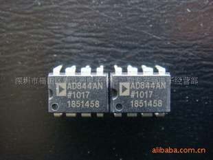
..back to purchasing AD844 from China, does anyone know...
An externally hosted image should be here but it was not working when we last tested it.
I just noted that the ones I received from China (HK) were labelled "Philippines" and the previous ones from Element14 are labelled "Malaysia" - both on the under/pin side.
.
This, of itself doesn't indicate an issue. The 'country of origin' marked on the package is the location where it was assembled and tested. It does not indicate where the wafer was fabricated. Most large semiconductor companies have multiple assembly and test factories, some owned and the others subcontractors. Many economic and practical factors (volume, technology, etc.) cause these to change over time.
I would expect that the ones purchased from Element14 are legitimate as they are a bona fide distributor. Ones purchased from China may or may not be, though the marking on the package is not the best indicator. Counterfeiters are often very good a duplicating marking schemes. The most sure way to know would be to etch open the package and look at the die, but even then I've seen counterfeit devices that were made with genuine, but rejected, die obtained somehow from the manufacturer's production flow.
I would expect that the ones purchased from Element14 are legitimate as they are a bona fide distributor. Ones purchased from China may or may not be, though the marking on the package is not the best indicator. Counterfeiters are often very good a duplicating marking schemes. The most sure way to know would be to etch open the package and look at the die, but even then I've seen counterfeit devices that were made with genuine, but rejected, die obtained somehow from the manufacturer's production flow.
What is the purchasing process of the distributors like Farnell, Mouser, etc !
Do they source from specialised big local wholesaler in Asia or direct with purchasers to the manufacter brand ? Or intermediate and independant local purchasing offices ?
Some local manufacturing subcontracting under licence from frontal parts brands could permitt to abuse the resellers like Farnel, Mouser, etc !
The manufacturing and supply chain could have a weak link and elude official distributors. those last not sure to have 100% genuine parts sometimes at delivry ?
 So little hifi brands could be abused as well ! You could buy an Acuphase with matched but non true output transistors !
Do they source from specialised big local wholesaler in Asia or direct with purchasers to the manufacter brand ? Or intermediate and independant local purchasing offices ?
Some local manufacturing subcontracting under licence from frontal parts brands could permitt to abuse the resellers like Farnel, Mouser, etc !
The manufacturing and supply chain could have a weak link and elude official distributors. those last not sure to have 100% genuine parts sometimes at delivry ?
So little hifi brands could be abused as well ! You could buy an Acuphase with matched but non true output transistors !"Do you have two PCM1704s per channel outputting anti-phase signals? If not then no, you won't have balanced circuitry. Only with balanced does the cancellation of currents into the 0V come, which relieves the need for decoupling to 0V."
...............
I believe the original circuit of this player was anti-phase, two PCM1704s. I didn't know how to implement the AD844 so I just disconnected the extra set. Any hints?
I had thought about the return path to the PCM1704s after writing the previous posts. I will have to take the board out to physically trace the return(double sided board). The original circuit was, shall I say, a mess. Asymmetrical layout, 3 pin regulator PS up to 22cm trace length to the audio section, 5 opamp output stage, and common decouple electolytic caps. Where is the balanced offsetting currents occurring in a anti-phase setup? At the dacs or at the AD844? I am curious, as the factory left off the ceramic decoupling caps near the dac chips. There was pads for them, but were never installed, but show on the service manual!
Member
Joined 2006
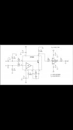
Anyone has tried this config?
(input stages identical in the OTA and buffer sections on chip)
Say make the input loads one ohm or less...
Does this chip have enough bandwidth to cope with the 9018?
(input stages identical in the OTA and buffer sections on chip)
Say make the input loads one ohm or less...
Does this chip have enough bandwidth to cope with the 9018?
Attachments
Last edited:
PCM1704 I/V ?
Hi George, Kind of fell of the earth for a while (an unwanted divorce). Did you try the OPA660 or OPA861? In my absence I did build a new preamp. A Pass BA-3 with Didden Super Regulators and dual mono power supplies. Using the Goldpoint attenuator device, for now. Super close matched JFET's. Recapped the MG2.5R crossovers which required reverse engineering the crossover schematic (my "cousins" not Magnepan's). Went with Jantzen Crosscaps. Well worth the effort. I am currently getting started on the "modular dac" project. Just started stuffing boards for a parallel "Red Baron" TDA1541A dac. So I am back looking at I/V choices again and running through the old forum entries.... The PCM 1704's are just begging to be built up too. Likely go with a double stack AD844's on that. Have you found anything better as far as I/V's? Best regards, Dave
HF noise level will be much higher without the cap, maybe this masks the hf and it sounds softer? or maybe because you use a 2000pf it maybe making the I/V stage output ring?
I calculate a -3db of 118khz with 2.7kohm and 500pf on pin 5 to analogue ground, I get very low noise after the BUF03 and my screenshots are here to view.
http://www.diyaudio.com/forums/digital-source/227677-using-ad844-i-v-8.html#post3338183
Cheers George
Hi George, Kind of fell of the earth for a while (an unwanted divorce). Did you try the OPA660 or OPA861? In my absence I did build a new preamp. A Pass BA-3 with Didden Super Regulators and dual mono power supplies. Using the Goldpoint attenuator device, for now. Super close matched JFET's. Recapped the MG2.5R crossovers which required reverse engineering the crossover schematic (my "cousins" not Magnepan's). Went with Jantzen Crosscaps. Well worth the effort. I am currently getting started on the "modular dac" project. Just started stuffing boards for a parallel "Red Baron" TDA1541A dac. So I am back looking at I/V choices again and running through the old forum entries.... The PCM 1704's are just begging to be built up too. Likely go with a double stack AD844's on that. Have you found anything better as far as I/V's? Best regards, Dave
No, still very keen on the sound of the 2 x stacked 844 (without using it's buffer stage) per channel and it's such an easy sub having the same voltage/pinout as what was originally there, (OPA627 as an I/V from the manufacturer).
I did sub my BUF03 buffer for an AD825 buffer though (I've always loved this opamp as a buffer), and it seems a bit cleaner, probably lower distortion because the AD825 is feedback operated where the BUF03 is not. And it still has great output grunt, 8ohms output impedance at up to 100mA, and is unity gain stable.
Cheers George
Does this chip have enough bandwidth to cope with the 9018?
Sure. But put a 68nF across the input on top of R3 and R7 and it makes a remarkable difference (something that has been name, not by me, as the Rasmussen Effect).
There is another advantage here, that the I/V current is not going through the "-" of the DT (or sometimes called OTA). There is no need to stack chips like they do with the 844's.
Sadly the OPA-660 is no longer current and replaced by the OPA-860.
Take a look at this - make a few changes and it can be used with OPA-660, simpler than above and no need for BUF chip.
Tweak R3 and you should be able to get DC offset near nil and no need for output cap C4. And omit C3 as it really isn't needed.
Cheers, Joe
.
Last edited:
No, still very keen on the sound of the 2 x stacked 844 (without using it's buffer stage)...
So you are using the I (current) output, right?
If you are using 1K5 on Pin 5, then make sure you are seeing a very high impedance or the gain will drop proprotionally. If you are seeing 10K, then the parallel value is 1K3 (x0.7666) and loss = 2.3dB.
Interesting, you can actually drive very low impedances, for example, drive 1K5 (=750R) and it will work, just allow a loss of -6dB. The output current from Pin 5 will always be the same. Even into a short. So it is not weak even if it looks weak, this is that nature of the thing as it outputs current and not volts.
Cheers, Joe
"So it is not weak even if it looks weak"
All else being equal, gains TZ loading etc. Every time I listen to the 844's own buffer,
compared to the AD825 (8ohms 100mA) or BUF03 (2ohms 70mA) the buffer stage of the 844 sounds weak, (60mA 15ohms).
You can hear it when compared to the BUF03 and AD825 as a slight lack of bass grunt and control, sounds a bit anemic/thin in comparison.
Cheers George
Member
Joined 2006
AD825
Hi George, Thanks for the tip on the AD825. I'll get a few on order in the next week or so. I didn't really like the AD844's buffer either. It is as you described it. The changes to my system has "highlighted" how nice the common base current mirrors can sound with the TDA1541 based dac's. I have the Saber dac in my Oppo BDP83 SE and other then an occasional SACD with that I don't use it much at all. Looking forward to experimenting with some other dac's. I have PCM1704, PCM1700, and AD1860 to try. I'll be using a more modular approach going forward."So it is not weak even if it looks weak"
All else being equal, gains TZ loading etc. Every time I listen to the 844's own buffer,
compared to the AD825 (8ohms 100mA) or BUF03 (2ohms 70mA) the buffer stage of the 844 sounds weak, (60mA 15ohms).
You can hear it when compared to the BUF03 and AD825 as a slight lack of bass grunt and control, sounds a bit anemic/thin in comparison.
Cheers George
After I talked to Dave More (alias Art Vandelay and very cluey) about the AD844 stacked. he also was impressed with it's sound.
He has been doing has been doing some measurements and progressed with this chip somewhat even more, with using it's buffer also stacked, and getting some very good measurement from it to back up what he's done. I'll get him join this forum to add his details here so others can progress it's great sound even more.
Cheers George
- Home
- Source & Line
- Digital Line Level
- Using the AD844 as an I/V