He he,,I remember Doede wrote that there was nothing to achieve with other regs for the digital side. But I’m willing to try anyway.
") It is indeed like that what I also mention on my web site at the introduction text for the "new dac boards". I left space for those who like to experiment !
It is indeed like that what I also mention on my web site at the introduction text for the "new dac boards". I left space for those who like to experiment !The reason I did not implement another two embedded Shunts on the dac boards was clearly to keep things under budget control and keep a critical eye on price / performance
The 8V shunt on the analog side gain in sound quality was (in my tests) so much more than with the digital side (3.3V) I decided against doubling the number of shunts for the basic version.
And indeed, now everyone can experiment as they wish and see if it is worth for their personal budget (Wallet) to squeeze out the last drop ?
After all - this is a hobby, right
...see if it is worth for their personal budget (Wallet) to squeeze out the last drop ?
After all - this is a hobby, right
Where else would I put my money?
yes….@Doede
Was it Tent lab shunts you tested on the digital side ?
cars?
No cars around here. Bicycles! Soldering frames and stuff, can get expensive...
Bass has better definition and the general sound is more dynamic. This was the first thing I noticed after the reg replacement. After a few hour’s with easy listening on the couch, it’s clear that this is quite an upgrade for small money.
If other will experience this reg change so strong that i did is impossible to say, but it’s well worth a try, and I feel quite sure that you will hear that something has happend.
Great, I have ordered one. Hoping to receive these benefits in my unit as well. Thanks for the inputs.
Tada....fits right in.
How does it sound?
Hello,
Some of you might know that i like to use chokes.
Doede made some simulations with my new acquired choke.
See the attachments.
Greetings, Eduard
Some of you might know that i like to use chokes.
Doede made some simulations with my new acquired choke.
See the attachments.
Greetings, Eduard
Attachments
Hello,
Some of you might know that i like to use chokes.
Doede made some simulations with my new acquired choke.
See the attachments.
Greetings, Eduard
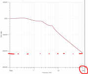
Thanks for posting Ed, so what we see here is the extreme damping at 3 nicely spread poles - Also that the final resulting output voltage is highly depending on the load current due to the high added up DC resistance value of the used chokes - so trimming necessary and finally that the impact of the bleeder is not as high as expected and hence not critical
to complete the story below is the actual circuit Ed is using with Choke numbers etc.
By the way, this is all done with Tina Basic 10
Attachments
Hello,
Some of you might know that i like to use chokes.
Doede made some simulations with my new acquired choke.
See the attachments.
Greetings, Eduard
Some of the axis labels are cut off, so the plots are not very meaningful. Can you update the plots with clear labels?
Also, an actual measurement would be useful to check what reality does with theory.
Some of the axis labels are cut off, so the plots are not very meaningful. Can you update the plots with clear labels?
Also, an actual measurement would be useful to check what reality does with theory.
sorry thought it was clear
First one: dB Damping from Input to Output
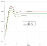
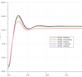
Next two: Output Volt versus time in Seconds versus Current load (with 1k2 bleeder) and the next one versus Bleeder value in Ohm (with 950mA)
so you see the PSU powers up with a short up/down and get stable round 12-13 Volt
Hello,
The 5 volt supply for the wave IO is a Belleson 5V 2A regulator fed by a2 times12 volt in parallel R core going into a 1 Henry 0,7A choke. So also choke input. The big choke i bought has a different version with 6 H at 0,5 A . If putting the 12 volts in series will give me enough ac to use this choke i am going to try it.
Doede told me that the load of the wave IO presented to the power supply is very stable so the extra dcr will not pose any problems.
The 12 volt supplies also doesnt care a lot about dcr because ofd the use of the Tent shunts.
Greetings, Eduard
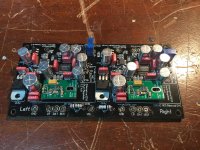
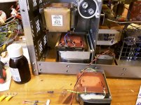
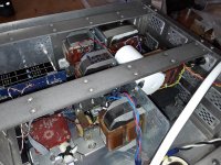
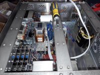
Hello,
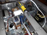
Just some photos to show there is still some space left to move the transformer for the 5 volt supply , remove the present ll2733 for the 5 volt supply( if voltage will be on the high side if i change the 2*12 volts from parallel to serie i might keep it there) and installing another LL2771 using the same construction used for the R core.
Greetings, eduard
Attachments
Hi Doede
I have older version Motherboard (RED) and older version dddac board
with resistors on input LR: 100R, DATA: 1K, BCK: 100R.
I want to upgrade to new Blue Motherboard.Do I need to change the values of these resistors on the older dddac board?
Yes, the Blue board has the half cycle delay built in so no need for the 1k resistor. better to replace this with 100 Ohm too
Thanks for posting Ed, so what we see here is the extreme damping at 3 nicely spread poles - Also that the final resulting output voltage is highly depending on the load current due to the high added up DC resistance value of the used chokes - so trimming necessary and finally that the impact of the bleeder is not as high as expected and hence not critical
to complete the story below is the actual circuit Ed is using with Choke numbers etc.
By the way, this is all done with Tina Basic 10
Interesting setup, but one concern for me would be the voltage output if current demand is reduced for some reason. Even if you powered up with the dac boards disconnected for some reason, such as testing or modifying, or made a wiring error for instance. You will then have only a 1.2k resistor loading that network of LC filters. You will surely get a high dc value from the 34vac rectified -maybe 50v and also could get much larger peak voltages during turn on. Would the filter caps survive this? It would be interesting to see a simulation for this scenario.
I would also check for peak output voltage in the actual breadboarded filter circuit using a dummy load to simulate the dacs before putting the circuit into service. Simulation software can be quite accurate but with so many chokes in the circuit, small errors in the inputted parameters may cause a different output peak in the startup response. For instance, the load in the simulation is a constant current source. However the current will not be constant during the voltage ramp up. If the startup voltage peak were to exceed the voltage capability of the load then the boards would be damaged.
Hello,
I have used choke input before with the dddac. Yes, this time the input choke has more Henry and more DCR so i had to change the 21 volt transformer into one which would allow me to create different different voltages and then i ended up with 34 volts. The bleeder is always there and there are two 5 watt zener diodes in serie to stop the voltage going over 30 volts. The first cap i use a 63 volt. There is the 7810 to protect the shunts.
I cannot imagine that all the 7810 brakdown at the same time.
A few days ago i already connected the new power supply for a few hours no sparks!!
Greetings, Eduard
- Home
- Source & Line
- Digital Line Level
- A NOS 192/24 DAC with the PCM1794 (and WaveIO USB input)