There are two modes of connection on I2SoverUSB (I2S like protocols on board oscillators and I2S like protocols with external MCLK ). Which one should I use ?
I2SoverUSB can operate with its own clocks, or from an external clock source. Simplest way is to let it use its own clocks which are already pretty low jitter. Also, the I2S and clock outputs are all galvanically isolated.
IIRC, all you need are the I2S signals going into FIFO_Pi. If you want to use I2SoverUSB without FIFO_Pi then you might want to enable the MCLK out pins. What I do is enable both the 22/24MHz and 45/49MHz clock outputs. Then I can them use or not, but they are there in case I want them. To do that, I install jumpers at B1, B2, and B3.
Last edited:
I2SoverUSB can operate with its own clocks, or from an external clock source. Simplest way is to let it use its own clocks which are already pretty low jitter. Also, the I2S and clock outputs are all galvanically isolated.
IIRC, all you need are the I2S signals going into FIFO_Pi. If you want to use I2SoverUSB without FIFO_Pi then you might want to enable the MCLK out pins. What I do is enable both the 22/24MHz and 45/49MHz clock outputs. Then I can them use or not, but they are there in case I want them. To do that, I install jumpers at B1, B2, and B3.
Thanks for the information .
IIRC, all you need are the I2S signals going into FIFO_Pi.
I have a fifopi that I just feed three I2S lines, Bclk, data and LRclk. Works great.
FWIW, I soldered a header into a little piece of protoboard, and plug the header into the bottom 40 pin connector of the fifopi.
The protoboard helps hold the header together. The plastic in the headers I have melts really easily when you solder wires to them, and sometimes the pins either come loose or get skewed.
In some previous post Ian made, he had said this, which I copied and saved:
For compensation, the resister values will be up to the real situation of the GPIO connector load and PCB trace impedance of the real application. They could be in a range of 100 to 500 ohm. I use 200 ohm 0402 chip resistors in the picture and they work fine. You could try some thing else for better result. Resistors in 0603 package are also good for easier soldering.
For compensation, the resister values will be up to the real situation of the GPIO connector load and PCB trace impedance of the real application. They could be in a range of 100 to 500 ohm. I use 200 ohm 0402 chip resistors in the picture and they work fine. You could try some thing else for better result. Resistors in 0603 package are also good for easier soldering.
Ian ,
Today I tried to connect the i2soverusb board to fifopi , I got the following on the display : WRONG 24.5785MHz .
What does it mean ?

Hi Rrbs,
It means that the format is not in 16, 24 or 32bit.
FifoPi works for any data length. FifoPi doesn't change the format of the music stream. What's in what's out. However, ESS DAC can not tolerance with the data length other than the three numbers above.
Or, trying better cables to see if the issue was caused by noise and cross talk related to cables and connections.
Regards,
Ian
Thanks for the information . I will try to secure the connections .
I2SoverUSB defaults to 32-bit, IIRC. That is to say, it zero pads something like 16-bit audio streams.
I would probably recommend to start testing with something easy like 16/44 CD rips. If that works, then move on to other formats.
If using a Windows PC to play audio, best to use ASIO drivers and make sure I2SoverUSB is not selected as the Windows default audio device, or the default communications device. If it is a default anything, then Windows will interfere and add distortion to many things one might try to play. Same problem if ASIO drivers are not used.
Last edited:
After some time not reading the forum, I feel I lost track somewhat.
Is it possible to have some kind of block diagram of the latest modules and maybe even a wiring diagram?
I would like te make a DAC (not sure yet which ESS-modules; Ian's or TPA's) with an input selection of 2 or 3 spdif, 1 USB, and 2 or 3 I2S. Reclocking, FIFO and DoP-decoder and the controller plus UC-power. I want the RPi to be separate (maybe even more RPi's with different tasks, therefore 2 or 3 I2S inputs).
Would be nice if someone can think along.
TransportPi for pure synchronized clock mode ROON transport
A pure synchronized clock mode ROON transport can be easily built by:
1. A TransportPi
2. A FifoPi Q2
3. A Raspberry Pi 4B
It will have:
1. An Isolated S/PDIF output in RCA
2. A non-isolated S/PDIF output in BNC (FifoPi already has built-in isolator)
3. A OPT S/PDIF in TOSLINK
4. A LVDS I2S/DSD/Dop output in HDMI
With ReceiverPi included, it can also become an all in one transport with built-in S/PDIF FIFO.
I'm very happy with the implement. I'll have more update soon.

TransportPiFifoPi2 by Ian, on Flickr

TransportPiFifoPi1 by Ian, on Flickr
Ian
A pure synchronized clock mode ROON transport can be easily built by:
1. A TransportPi
2. A FifoPi Q2
3. A Raspberry Pi 4B
It will have:
1. An Isolated S/PDIF output in RCA
2. A non-isolated S/PDIF output in BNC (FifoPi already has built-in isolator)
3. A OPT S/PDIF in TOSLINK
4. A LVDS I2S/DSD/Dop output in HDMI
With ReceiverPi included, it can also become an all in one transport with built-in S/PDIF FIFO.
I'm very happy with the implement. I'll have more update soon.
TransportPiFifoPi2 by Ian, on Flickr
TransportPiFifoPi1 by Ian, on Flickr
Ian
Last edited:
Hi Ian,
Which software do you currently use for ROON? These HATS will work with allo usbridge signature as well right?
Yes, Greg mounted them on a usb sig.
I run a usb sig through usb to my stack.
Hi Ian,
Which software do you currently use for ROON? These HATS will work with allo usbridge signature as well right?
@tubo,
I use both RoPieee and Volumio.
RoPieee will be easier to install.
But I like Volumio more because it has more functions additional to ROON endpoint. I can also use Volumio to play music on my DLNA server and so on. Very flexible. But to install ROOM endpoint on Volumio could be a little bit complicated but not really difficult. I can post a tutorial if you are interested in.
Greg confirmed that all my gears works with Usbridge. I don't think there is any problem.
Regards,
Ian
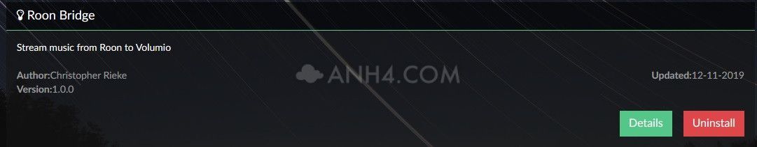
Volumio ver 2.668 already has the roon bridge plugin .
Download |Get Started | Volumio
Download |Get Started | Volumio
An externally hosted image should be here but it was not working when we last tested it.
- Home
- Source & Line
- Digital Line Level
- Asynchronous I2S FIFO project, an ultimate weapon to fight the jitter