Buffalo IIIsePro firmware bug and solution
1. Issues of Buffalo IIIsePro
Ofswitched has two BIIIsePro DACs. But with the default switch settings, none of them works correctly at both 16bit and 32bit I2S input signals, even without FifoPi. He gave a lot of try but still cannot make it. I have a BIIIse, I don’t have any problem. I was wondering what’s wrong with BIIIsePro.
I’m not responsible for debugging user’s system. But finally I decided passing a hand to provide some help.
When I received the package, I installed one of them into my system. Yes, the issue was confirmed. It doesn’t work for any I2S input. A lot of noise with 32bit input and almost no sound with 16bit input. However DSD was playing correctly. All switch settings were at “OFF” position which was as Twistedpear default. Those setting should be for:
Switch1: PCM/DSD – I2S -32bit - Brickwall
Switch2: AutoMute – disable – 70K – highest
I need to figure out what’s the problem.
2. Firmware bug
Thanks twistedpear, they posted the source code of BIIIsePro firmware to gitHub, which is here:
GitHub - twistedpearaudio/Buffalo-III-SE-Pro-On-Board-Firmware
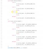
When I went through the code, I immediately found a bug, please see the first picture attached.
With this bug, as default, when switch1.2-3 was set at both off positions, the actual PCM format that the BIIIsePro will take would be the right justified, not the I2S it should be (according to the user’s manual). That explains why I2S inputs were always wrong.
Based on the source code, I should have solution to fix the issue
3, Solution to avoid this bug
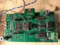
To avoid the bug, for default, set switch1 to: off, on, on, on, on, off, off, off. While keep swhich2 to all off position.
The issue fixed! 32bit I2S music plays correctly, as well as DSD music. (For 16 bit I2S music, just needs to enable 16 to 32 bit convertor on FifoPi.)
Please see second picture for correct switch settings.
Ian
1. Issues of Buffalo IIIsePro
Ofswitched has two BIIIsePro DACs. But with the default switch settings, none of them works correctly at both 16bit and 32bit I2S input signals, even without FifoPi. He gave a lot of try but still cannot make it. I have a BIIIse, I don’t have any problem. I was wondering what’s wrong with BIIIsePro.
I’m not responsible for debugging user’s system. But finally I decided passing a hand to provide some help.
When I received the package, I installed one of them into my system. Yes, the issue was confirmed. It doesn’t work for any I2S input. A lot of noise with 32bit input and almost no sound with 16bit input. However DSD was playing correctly. All switch settings were at “OFF” position which was as Twistedpear default. Those setting should be for:
Switch1: PCM/DSD – I2S -32bit - Brickwall
Switch2: AutoMute – disable – 70K – highest
I need to figure out what’s the problem.
2. Firmware bug
Thanks twistedpear, they posted the source code of BIIIsePro firmware to gitHub, which is here:
GitHub - twistedpearaudio/Buffalo-III-SE-Pro-On-Board-Firmware
When I went through the code, I immediately found a bug, please see the first picture attached.
With this bug, as default, when switch1.2-3 was set at both off positions, the actual PCM format that the BIIIsePro will take would be the right justified, not the I2S it should be (according to the user’s manual). That explains why I2S inputs were always wrong.
Based on the source code, I should have solution to fix the issue
3, Solution to avoid this bug
To avoid the bug, for default, set switch1 to: off, on, on, on, on, off, off, off. While keep swhich2 to all off position.
The issue fixed! 32bit I2S music plays correctly, as well as DSD music. (For 16 bit I2S music, just needs to enable 16 to 32 bit convertor on FifoPi.)
Please see second picture for correct switch settings.
Ian
Attachments
Last edited:
Which Benchmark DAC-3 do you have?
Benchmark DAC-3 HGC
Benchmark DAC3 HGC D/A preamplifier-headphone amplifier | Stereophile.com
Benchmark DAC3 HGC - Digital to Analog Audio Converter - Benchmark Media Systems
Recommended Components: 2019 Edition Digital Processors | Stereophile.com
Last edited:
1. Issues of Buffalo IIIsePro
Ofswitched has two BIIIsePro DACs. But with the default switch settings, none of them works correctly at both 16bit and 32bit I2S input signals, even without FifoPi. He gave a lot of try but still cannot make it. I have a BIIIse, I don’t have any problem. I was wondering what’s wrong with BIIIsePro.
I’m not responsible for debugging user’s system. But finally I decided passing a hand to provide some help.
When I received the package, I installed one of them into my system. Yes, the issue was confirmed. It doesn’t work for any I2S input. A lot of noise with 32bit input and almost no sound with 16bit input. However DSD was playing correctly. All switch settings were at “OFF” position which was as Twistedpear default. Those setting should be for:
Switch1: PCM/DSD – I2S -32bit - Brickwall
Switch2: AutoMute – disable – 70K – highest
I need to figure out what’s the problem.
2. Firmware bug
Thanks twistedpear, they posted the source code of BIIIsePro firmware to gitHub, which is here:
GitHub - twistedpearaudio/Buffalo-III-SE-Pro-On-Board-Firmware
When I went through the code, I immediately found a bug, please see the first picture attached.
With this bug, as default, when switch1.2-3 was set at both off positions, the actual PCM format that the BIIIsePro will take would be the right justified, not the I2S it should be (according to the user’s manual). That explains why I2S inputs were always wrong.
Based on the source code, I should have solution to fix the issue
3, Solution to avoid this bug
To avoid the bug, for default, set switch1 to: off, on, on, on, on, off, off, off. While keep swhich2 to all off position.
The issue fixed! 32bit I2S music plays correctly, as well as DSD music. (For 16 bit I2S music, just needs to enable 16 to 32 bit convertor on FifoPi.)
Please see second picture for correct switch settings.
Ian
Ian is genius.
@ Markw4,
Thank you so much!
Ian
1. Issues of Buffalo IIIsePro
Ofswitched has two BIIIsePro DACs. But with the default switch settings, none of them works correctly at both 16bit and 32bit I2S input signals, even without FifoPi. He gave a lot of try but still cannot make it. I have a BIIIse, I don’t have any problem. I was wondering what’s wrong with BIIIsePro.
I’m not responsible for debugging user’s system. But finally I decided passing a hand to provide some help.
When I received the package, I installed one of them into my system. Yes, the issue was confirmed. It doesn’t work for any I2S input. A lot of noise with 32bit input and almost no sound with 16bit input. However DSD was playing correctly. All switch settings were at “OFF” position which was as Twistedpear default. Those setting should be for:
Switch1: PCM/DSD – I2S -32bit - Brickwall
Switch2: AutoMute – disable – 70K – highest
I need to figure out what’s the problem.
2. Firmware bug
Thanks twistedpear, they posted the source code of BIIIsePro firmware to gitHub, which is here:
GitHub - twistedpearaudio/Buffalo-III-SE-Pro-On-Board-Firmware
When I went through the code, I immediately found a bug, please see the first picture attached.
With this bug, as default, when switch1.2-3 was set at both off positions, the actual PCM format that the BIIIsePro will take would be the right justified, not the I2S it should be (according to the user’s manual). That explains why I2S inputs were always wrong.
Based on the source code, I should have solution to fix the issue
3, Solution to avoid this bug
To avoid the bug, for default, set switch1 to: off, on, on, on, on, off, off, off. While keep swhich2 to all off position.
The issue fixed! 32bit I2S music plays correctly, as well as DSD music. (For 16 bit I2S music, just needs to enable 16 to 32 bit convertor on FifoPi.)
Please see second picture for correct switch settings.
Ian
Thanks for bringing this to my attention! There is an error there to be sure - but thankfully the error simply results in case 2 and 3 (on/off, off/off) being transposed. I will correct the documentation and the code to reflect that.
The good news is that by default all of the switches are in the "on" (0) position. So the default format is actually I2S. So as long as you disable SPDIF input (switch 1 position 1 to off) you will be fine for I2S. Most of our users use the first case - which is why this scenario has not been seen by me until now. 🙂 We have lots of folks using I2S of course.
Cheers!
Russ
The code and the README have been updated. Thanks again! Users need not change firmware - just follow the updated README if you want to use RJ format (or non-default I2S format) . For I2S/32bit I recommend using the default "0" case for both format and word size size it requires less switch flipping anyway. 🙂
Cheers!
Russ
Cheers!
Russ
Thanks for bringing this to my attention! There is an error there to be sure - but thankfully the error simply results in case 2 and 3 (on/off, off/off) being transposed. I will correct the documentation and the code to reflect that.
The good news is that by default all of the switches are in the "on" (0) position. So the default format is actually I2S. So as long as you disable SPDIF input (switch 1 position 1 to off) you will be fine for I2S. Most of our users use the first case - which is why this scenario has not been seen by me until now. 🙂 We have lots of folks using I2S of course.
Cheers!
Russ
Thanks Russ for your fast response.
I have two Buffalo DACs. You did good job. I'm happy with them.
Regards,
Ian
Thanks for bringing this to my attention! There is an error there to be sure - but thankfully the error simply results in case 2 and 3 (on/off, off/off) being transposed. I will correct the documentation and the code to reflect that.
The good news is that by default all of the switches are in the "on" (0) position. So the default format is actually I2S. So as long as you disable SPDIF input (switch 1 position 1 to off) you will be fine for I2S. Most of our users use the first case - which is why this scenario has not been seen by me until now. 🙂 We have lots of folks using I2S of course.
Cheers!
Russ
The part you mentioned now seems to just make the switch more compliant with the settings in the firmware. However, the problem I encountered was not that the I2S input signal could not be sent to the DAC, but the noise was generated when the 16-bit depth signal was transmitted via I2S. In other words, the bug pointed out by Ian is actually only a small part.
Last edited:
16/24/32bit I2S formats all play just fine if you have the switches set correctly. I have verified the same for RJ and LJ. You might need to check your source.
I am not having - nor have I heard any instances of anyone having any issues playing 16/24/32bit samples of any supported format. The firmware is open source - so I welcome Issues/Pull Requests if someone sees something amiss (or even that just needs clarifying) like the small error above which was addressed in about 5 minutes of me seeing it.
Fortunately almost nobody (the one exception I know of excluded) would have been affected by that error as the default switch positions are "on" and you would have to actually work at trying the second I2S option. 🙂 Most people would go with the initial (default) option which is already I2S.
@ ofswitched
I'll post the setup of BIII SE Pro with FifoPi, LifePO4 power supply and GB I/V board. You can use those set up directly when you get them.
It's not necessary to upgrade to the new firmware.
Ian
I'll post the setup of BIII SE Pro with FifoPi, LifePO4 power supply and GB I/V board. You can use those set up directly when you get them.
It's not necessary to upgrade to the new firmware.
Ian
Buffalo III SE pro works with FifoPi, LifePO4 power supply and my transformer I/V
Before I return the Buffalo III SE pro back to Ofswitched, I’d like to share with you what the setup I did to make it working with FifoPi, the LifePO4 pure battery power supply and the transformer I/V.
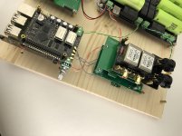
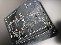
Buffalo III SE Pro was running at synchronized mode with MCLK and all other digital audio signals fed from FifoPi through u.fl cable. DPLL bandwidth can be set at lowest in this mode. Please see the first picture for the whole system set up.
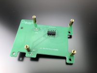
1. BIII SE pro power supply
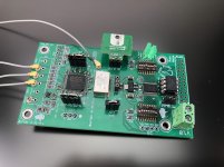
To make it works with 3.3V LifePO4 power supply, I did
a. Jump (short) VD to DVCC and AVCCV for both left and right channel
b. Use a 1.2V LT3042 low noise regulator
c. Short IN and OUT of DVCC 3.3V
d. Short the in and out of MCU regulator with FB.
e. Leave VDD_XO empty without connecting anything for sync mode.
Please see the second picture for details
Note: For best sound quality, I’m strongly suggested powering them with independent rails for the real DAC application.
2. BIII SE jumper set up
Please see the second picture for swith1 and siitch2 setup for details, the setting will be
PCM/DSD
I2S
32bit
Apodizing fast roll-off, minimum phase
Automute enable
OSF enable
47.44 KHz
Lowest bandwidth
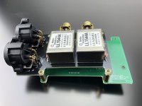
3. FifoPi switch jumper settings
Both S1.1 and S1.2 was set to “ON” position, which will
a. Enable 16 to 32 convertor
b. Use ES9038Pro internal DoP decoder
Please see the third picture for details
4. Use Buffalo I/V adapter in the reverse way to adapt Ian transformer I/V board to Buffalo DAC.
Please see the rest pictures for details
Note, value of resistors need to be reduced to match higher output current of ES9038Pro.
Ian
Before I return the Buffalo III SE pro back to Ofswitched, I’d like to share with you what the setup I did to make it working with FifoPi, the LifePO4 pure battery power supply and the transformer I/V.
Buffalo III SE Pro was running at synchronized mode with MCLK and all other digital audio signals fed from FifoPi through u.fl cable. DPLL bandwidth can be set at lowest in this mode. Please see the first picture for the whole system set up.
1. BIII SE pro power supply
To make it works with 3.3V LifePO4 power supply, I did
a. Jump (short) VD to DVCC and AVCCV for both left and right channel
b. Use a 1.2V LT3042 low noise regulator
c. Short IN and OUT of DVCC 3.3V
d. Short the in and out of MCU regulator with FB.
e. Leave VDD_XO empty without connecting anything for sync mode.
Please see the second picture for details
Note: For best sound quality, I’m strongly suggested powering them with independent rails for the real DAC application.
2. BIII SE jumper set up
Please see the second picture for swith1 and siitch2 setup for details, the setting will be
PCM/DSD
I2S
32bit
Apodizing fast roll-off, minimum phase
Automute enable
OSF enable
47.44 KHz
Lowest bandwidth
3. FifoPi switch jumper settings
Both S1.1 and S1.2 was set to “ON” position, which will
a. Enable 16 to 32 convertor
b. Use ES9038Pro internal DoP decoder
Please see the third picture for details
4. Use Buffalo I/V adapter in the reverse way to adapt Ian transformer I/V board to Buffalo DAC.
Please see the rest pictures for details
Note, value of resistors need to be reduced to match higher output current of ES9038Pro.
Ian
Attachments

Still waiting for a reply
Hi Ian,
I have written several times in the thread about removing the LDOs from the Dual XO board and the I2S to PCM converter, but still no response.
As I said I need to remove all LDOs and other unuseful parts from the above boards, that will be powered by LiFePo4 batteries.
As you well know your devices are all commercial projects, you have not shared any schematic and/or BOM, so we have no chance to understand what parts have to be removed to power directly by batteries avoiding any parts on the supply path.
As a customer, like all other members that have bought your stuff, I expect a service after sales.
Please, let us know how we can remove all the unuseful parts on the supply path to power directly the boards with batteries.
In other words, please provide detailed instructions about removing LDOs and other unuseful parts from Dual XO board and I2S to PCS converter.
Thanks in advance
Andrea
What’s required is a guide for connecting Ian’s battery supply module with his other products. LDOs may not need to be removed on all boards - I don’t know though.
A pure battery power supply needs all LDOs and other unuseful parts to be removed from the power path.
There is no reason to keep in place unuseful parts that affects the batteries performance.
Since no schematic has been shared, I simply ask for detailed instructions.
There is no reason to keep in place unuseful parts that affects the batteries performance.
Since no schematic has been shared, I simply ask for detailed instructions.
Last edited:
Waiting for reply
Hi Ian,
is there any chance that sooner or later you answer my question (not just mine) providing detailed instructions about removing LDOs from Dual XO board and I2S to PCM converter?
I will appreciate your help
Andrea
Hi Ian,
is there any chance that sooner or later you answer my question (not just mine) providing detailed instructions about removing LDOs from Dual XO board and I2S to PCM converter?
I will appreciate your help
Andrea
Hi Ian,
I would use your devices to test my new segmented R2R discrete DAC in this way:
- FIFO Buffer, powered with 5VDC linear regulator
- Isolator Adapter, input stage powered with the above 5VDC linear regulator, output stage powered with 3V3 LiFePo4 batteries
- Dual XO board with external oscillators, powered with the same 3V3 LiFePo4 batteries
- I2S to PCM converter, powered with the same 3V3 LiFePo4 batteries
I would exclude all LDOs and all other unuseful parts on the power path of the devices that will be batteries powered.
In other words I would remove LDOs and other unuseful parts on the power path from Dual XO board and I2S to PCM converter, to power them directly with batteries.
Thanks
Andrea
@ andrea_mori
You can do it this way no any problem. It would be great. That's the reason I designed the upgrade-able LDO boards.
To keep the LifePO4 battery power supply performance, please use bigger wires. Because the batteries are passive power supply without any feedback.
Regards,
Ian
You can do it this way no any problem. It would be great. That's the reason I designed the upgrade-able LDO boards.
To keep the LifePO4 battery power supply performance, please use bigger wires. Because the batteries are passive power supply without any feedback.
Regards,
Ian
Hi Ian,
Ok, I understand I can do this way, but I would know what parts I have to remove (LDOs and other components on the power path).
I would get pure battery powered way.
Please, let me know.
Thanks
Andrea
Ok, I understand I can do this way, but I would know what parts I have to remove (LDOs and other components on the power path).
I would get pure battery powered way.
Please, let me know.
Thanks
Andrea
- Home
- Source & Line
- Digital Line Level
- Asynchronous I2S FIFO project, an ultimate weapon to fight the jitter