It is board with DAC, of course analog power supply is separated. This spikes seen after LT3045 on 1.0V XMOS power rail, seems to be strange for such good regulator, anyway it sounds very good instead of PWM regulator. I'll try to power it from separate 1.5V transformer winding, may be LT behaves like this because of big voltage drop from 5V to 1VWhich PCB are you using? One way to avoid processor switching noise in the analog circuits is to have completely separate power traces for digital and analog, along with sufficient bypass filtering on all chips - both digital and analog. One common practice is to place two different capacitor values in parallel - the frequencies that one cap lets through will be filtered by the other. Bottom line: Since the processor draws a spike of current on every clock pulse, the power rail voltage (both power and ground) will see the increased voltage drop due to that current spike
As a result of experiments, I came to the conclusion that the most striking result is given by separation of power supply of VDD(core) and PLL_AVDD rails. Awesome improvement for sound. Now using two 1.0V regulators for these rails. It may be very usefull to users with different versions of XMOS, just look at schematics and datasheet (btw there is an simplified schematics in it, where these power supply pins are using the same regulator, but in text there mentioned that "The PLL_AVDD supply should be separated from the other noisier supplies on the board. The PLL requires a very clean power supply").

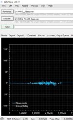
And here it is a difference even between regulators at PLL_AVDD.
Both powered by main linear supply with TPS7A4701, in both cases RC 4.7R+10uF are present at PLL_AVDD. In first case 1V for core and PLL_AVDD is made by 1117-3.3V > AP7365-10YG-13, in second by LT3045.
Both powered by main linear supply with TPS7A4701, in both cases RC 4.7R+10uF are present at PLL_AVDD. In first case 1V for core and PLL_AVDD is made by 1117-3.3V > AP7365-10YG-13, in second by LT3045.
Attachments
Last edited:
Did you try comparing two subsequent measurements with the same regulator? Did several measurements of the two regulators display similar difference? Thanks.And here it is a difference even between regulators at PLL_AVDD.
I wrote in another thread:
But as for me, more than 12 years, since I started to play with XMOS CPUs, I use 1117-3.3 and 1117-1.8 or LM3671 for digital power and AP7365 or TPS72010 for the core power (1.0v), with TPS3106K33 supervisor.
PLL is powered through 5.1 Ohm resistor and have 4.7uF X7R cap.
And had no problem yet.
P.S. Ans as I mentioned in another thread - all my USB interfaces have the external audio clock and galvanic isolation between USB and audio parts.
Alex.
There is no problems, it works good in both cases. There is an audible difference.And had no problem yet.
No.There is an audible difference.
It was YOU, who said that there is an audible difference!
And others may say it doesn't.
A double blind test would show everything, but audiophiles always run from it like the devil from incense.
Alex.
@
Lucian (Lorien on this forum)
Anatolii_A:
Since I strongly feel this will spark a new debate, it would be advisable to open a new thread where you can post your findings, as this one is related to another build that can be seen in the first post of this discussion. There are other threads dedicated to discussing various improvements in XMOS implementations — my own approaches are listed in the first thread, including my take on how things can be implemented in hardware. As I said, any new ideas or approaches should be discussed separately to avoid confusion.Lucian (Lorien on this forum)
It seems that I permanently bricked my board by flashing it toWaveIO_v6.F2firmware. (before flashing I rundfucons revertfactorycommand)
After that it is not recognized byTUSBAudioDfu.exenor as linux usb device.
The same procedure worked many time before...
Is there a way to resurrect it by some other method? i.e. by short-circuit two pins on the xmos chip 😬
@Lorien, I replaced chip you sent and my board is alive again 🙌
⭐⭐⭐⭐⭐ for customer support, thank you!
Hi all,
My Wave IO had been consistently serving my DAC for several years until yesterday when it suddenly stopped. It turns on and is recognized both in Windows and Linux but there is no I2S output. However, it seems the problem only exists at the isolated outputs. I do get signal at the non isolated BNC. So, is it plausible to assume that the isolator chip is dead? It's easy to replace it but before I do anything, I would like to have your opinion.
My Wave IO had been consistently serving my DAC for several years until yesterday when it suddenly stopped. It turns on and is recognized both in Windows and Linux but there is no I2S output. However, it seems the problem only exists at the isolated outputs. I do get signal at the non isolated BNC. So, is it plausible to assume that the isolator chip is dead? It's easy to replace it but before I do anything, I would like to have your opinion.
Hello,
most likely the IL715-3E isolator chip is damaged (doesn't have to be the whole chip but at least 1 channel out of 4). If you want to know if a particular channel is drop dead then a small test can be done by measuring the voltage at its outputs with music playing. If you multimeter can read at least "something" as voltage then you can suppose it's okay otherwise... not. Make sure the chip is powered first! BUT there were cases when ESD discharges did messed up something on the chip itself and the supposedly "squared" signals were more like rounded and the reference voltage (0V/GND) was more like half of 3.3V. The multimeter approach can't help you on that!
P.S. Removing the chip with a soldering station would be the best approach. I would avoid using hot air there since pin-header connector is close to the chip.
- Home
- Source & Line
- Digital Line Level
- XMOS-based Asynchronous USB to I2S interface