Yes I came across the drawing on page 13 before.
So if I'm correct L+ and R+ are connected to ground through a capacitor, it's value to be determined by experimentation.
Then L- and R- become the left and right output?
What are the requirements of the capacitors? Should they be polypropylene or even more exotic?
While determining what value is best, what should I pay attention to?
Attachments
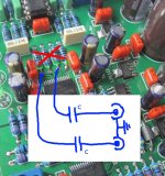
Not to ground. Pic shows L+ n R+ to centre of rca sockets.
If your preamp does not already have a input cap, I think 1uF ~3.3uF should be about right.
Choice of cap depends on $$ you want to spend
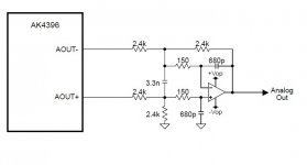
Looking at the ak4393 datasheet page 20 figure 12, external LPF with balanced and unbalanced options, it shows the DAC output goes into 47uF caps. That's quite a large value for film caps. Doable but still pretty large compared to the 3.3uF you mentioned.
Yep sounds free when you bypass LPF and Opamps, technically its not recommended but its the best way to listen to this Dac in my opinion.
Isn't the low pass filter needed? My active crossover will have balanced inputs, curious if I can drop the unbalanced conversion from the DAC.
Also how would you implement stereo volume control for balanced signal.
Last edited:


Seems like dropping the cap is ok, removes the high pass filter. If you have some DC you can remove it later in the chain where it's more convenient. But before volume control.
Also I tweaked the low pass filter cap from 10nF to 11nF and seems pretty linear this way:

Also I tweaked the low pass filter cap from 10nF to 11nF and seems pretty linear this way:
Last edited:
Seems like I can make a small shield to convert to balanced output. It has the same type of filter, just that it uses two LME49724 opamps.
Basically I'm using the same filter parts, most of the parts used I'll recover from the DAC pcb, I just need the opamps and 4 100ohm resistors.
I also added footprints for 8mm wide electrolytic caps. Looks kinda botched in but it will work just fine.
I just need to add some links on the pcb in place of the removed parts that I'll use on the shield, so I get the required signals on the original opamp socket. Also I need to use an extender so I can clear some caps on the DAC board.
Here's some renders:


I just need to get two sets of mini xlr connectors. They'll fit just fine in the original DAC case that it was sold originally with on ebay. Just that I need to drill two new holes for them, vertically, next to the RCA ones. This way they clear the shield.

I also made a version for dual opamps but it's a bit larger as it uses extra parts but I think I'm gonna go for LME49724.
Basically I'm using the same filter parts, most of the parts used I'll recover from the DAC pcb, I just need the opamps and 4 100ohm resistors.
I also added footprints for 8mm wide electrolytic caps. Looks kinda botched in but it will work just fine.
I just need to add some links on the pcb in place of the removed parts that I'll use on the shield, so I get the required signals on the original opamp socket. Also I need to use an extender so I can clear some caps on the DAC board.
Here's some renders:
I just need to get two sets of mini xlr connectors. They'll fit just fine in the original DAC case that it was sold originally with on ebay. Just that I need to drill two new holes for them, vertically, next to the RCA ones. This way they clear the shield.
I also made a version for dual opamps but it's a bit larger as it uses extra parts but I think I'm gonna go for LME49724.
The lme49724 is a nice chip, but you may kill it with that layout. Not much airflow and it appears you haven't followed any recommendations for the use of its powerpad. Another thing, it looks like you are relying on the decoupling caps on the existing pcb ic socket power supply pins? Your layout places the 49724 a long way from the socket; those caps will be useless to you. If you can't stomach ceramic decoupling caps, you can get suitably sized SMD pps film caps. Personally I'd use those in place of the wimas you have on the board as well; but that's just me.
Last edited:
I used a film cap to decouple the positive and negative rail (the single one on the top of each opamp, there's no cap to ground apart from the electrolytic ones. That's how I have it now anyway. I replaced the decoupling caps to ground with electrolytic ones on the DAC pcb, since the beginning. Also the board is like 33mm X 33mm. Also that decoupling cap will get installed on the bottom. Maybe the rest of the caps as well. There's enough room to not touch the DAC pcb.
I wasn't aware that lme49724 has a powerpad. Will try to adjust the layout. How much current does it gulp? The 100 ohm output resistors would limit the current to 20mA for 2V rms, all across the resistor in case of a short in the cable.
edit:
Checked the datasheet, 80mA max but I have those 100 ohm resistors installed anyway.
Here's how it looks like with the caps on the bottom (the ones from back from the outsides of the board will need to be kept up, they don't clear the electrolytic caps on the DAC pcb, the ones in the center can be installed on the bottom tho):


Also, part of the output filter remains on the DAC pcb, I only carried over what couldn't be left on the DAC pcb. The 3.3n caps I didn't carry over.
Here's how it needs to be done:

And on the schematic:

So in the end it's like this for the original opamp socket:

I wasn't aware that lme49724 has a powerpad. Will try to adjust the layout. How much current does it gulp? The 100 ohm output resistors would limit the current to 20mA for 2V rms, all across the resistor in case of a short in the cable.
edit:
Checked the datasheet, 80mA max but I have those 100 ohm resistors installed anyway.
Here's how it looks like with the caps on the bottom (the ones from back from the outsides of the board will need to be kept up, they don't clear the electrolytic caps on the DAC pcb, the ones in the center can be installed on the bottom tho):
Also, part of the output filter remains on the DAC pcb, I only carried over what couldn't be left on the DAC pcb. The 3.3n caps I didn't carry over.
Here's how it needs to be done:
And on the schematic:
So in the end it's like this for the original opamp socket:
Last edited:


Yeah. Pending clearance I was going to suggest mounting all the caps on the other side, then use thermal vias to connect to the copper pour (edited, forgot its vee not gnd) and flip the whole thing over. Honestly, depending on the load you are driving and provided the design is stable, you could maybe not worry about the thermal vias, but since you are doing the layout, why not?
I have more experience with the ti part (opa1632) than the 49724, but it certainly can get toasty in the SOIC Package (no powerpad) vs the same chip in msop (has powerpad). I use the 1632 as I have a bunch and the cost is similar with slightly better performance. It's EOL, but is still pretty easy to find.
The calc for dissipation will depend on your load and the quality of your layout (stability) the calc is in the datasheet in the notes at the bottom on page 3.
I would place a 0805 or 0603 ceramic as close to the power supply pins as possible.
Last edited:
Ha! Cross posted.
yes that should do it. You just gonna leave the pad unsolderwd? I'm sure it will cope, it's just that if you place 5 largish vias in the powerpad, you can use them to solder from under the board if you are lacking reflow /rework equipment. That way they serve double duty.
Or can I just not see the vias as they are covered by the decoupling now?

Cool, yeah that'll be fine. Re decoupling, in this case I would stick with rail to gnd. I'm not going to nitpick anymore as it's looking fairly good and I don't have time for involved advice (4 layer vs 2 and thin film or melf smd resistors) but for future layouts it's interesting that a power plane is generally just as good as ground for shield pours. Using a layer that is split up into vcc and vee copper pours can help keep everything nice and low impedance.
I did a test board on 4 layers for a version with 4 single opamps. It was getting crazy on two layers.
Gonna think about it. 4 layers is pretty cheap these days. Also maybe gonna replace the rail to rail decoupling cap with a 0805 as well, or parallel the footprint. Thank you for the tips! Surely I wouldn't have seen the powerpad.
Gonna think about it. 4 layers is pretty cheap these days. Also maybe gonna replace the rail to rail decoupling cap with a 0805 as well, or parallel the footprint. Thank you for the tips! Surely I wouldn't have seen the powerpad.
The capacitors are removing any DC from the outputs. You can omit them if you do remove the DC at some point. Usually preamps/amps have input caps that take care of the DC. But you need to try and see where it gets removed in the chain. It is good to do it before the volume pot.
You can use the circuit from post #3007
You can use the circuit from post #3007
- Home
- Source & Line
- Digital Line Level
- DAC 2496 (AK4393) DAC KIT With CS8416+AK4393+5532