Preamp: is Audio Research SP9 build 1978
You probably mean 1988. Or alternatively an SP6.
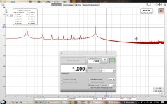
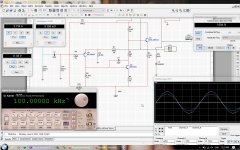
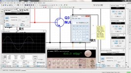
Sgnal to Noise and Distortion using REW
Hi Gents
anyone who's a specialist for REW Room EQ Wizard may take a look at it.
Setup is follwing:
Generator of REW setting to 1000Hz or 1k with -30 DB
Then SPL loocked at 9db for RTA Measurements
Output Poweramp to input MACBookPro switched and calibrated to LINE INPUT Sound Card Cirrus Logic CS4206 - Dummy Load 8 Ohm direct to Line inpput
Ouptut Sound Card Cirrus Logic - Set to Head Phone for output signal - to Input Poweramp
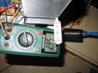
Poweramp set to MAX out put 13.8 Volt before Clipping because the AMP was already hot = 68C on the lower part of the heat sink
I got some Hum because of some connections which of course we can see in the Noise to THD measurements. But in regulary mode there is no HUM
But THD Measuernents are really good.. on full load as well on 1 Watt almost the same and this all over the full specturum as fas as I can Judge.
Now, I'm not a specialist for REW and that's why I place this here for all the Specialists to take a look at.
Any comment is welcome. BTW this is Class A single End full transistorized
Thanks for reading and eventually input..
Hi Gents
anyone who's a specialist for REW Room EQ Wizard may take a look at it.
Setup is follwing:
Generator of REW setting to 1000Hz or 1k with -30 DB
Then SPL loocked at 9db for RTA Measurements
Output Poweramp to input MACBookPro switched and calibrated to LINE INPUT Sound Card Cirrus Logic CS4206 - Dummy Load 8 Ohm direct to Line inpput
Ouptut Sound Card Cirrus Logic - Set to Head Phone for output signal - to Input Poweramp
Poweramp set to MAX out put 13.8 Volt before Clipping because the AMP was already hot = 68C on the lower part of the heat sink
I got some Hum because of some connections which of course we can see in the Noise to THD measurements. But in regulary mode there is no HUM
But THD Measuernents are really good.. on full load as well on 1 Watt almost the same and this all over the full specturum as fas as I can Judge.
Now, I'm not a specialist for REW and that's why I place this here for all the Specialists to take a look at.
Any comment is welcome. BTW this is Class A single End full transistorized
Thanks for reading and eventually input..
Attachments
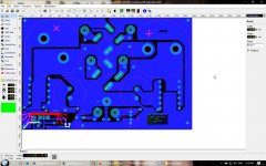
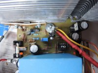
Hi Guys
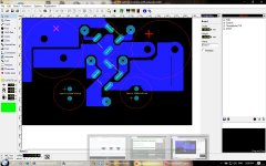
Now drawing the Artwork for the Powersupply PCB.
I'm on it for about 4 hours already because was in need to measure the involved components and safe them to the Art Program, so that these parts will fit on the PCB afterwards.
PSU is going to include also the Fan Control Unit for one side of the Amplifier as well as a Speaker Protection. The other Channel has its own PSU as this Amplifier contains TWO MONOBLOCKS. only Powerswitch and Case is used by both channels.and main Cable.. but may I separate the main cable as well
Fan Control:
Uses a Thermistor to switch a Transistor to turn the on the FAN. After reaching 75C the Thermistor will open and with this enable the BASE of the Transistor to switch the Fan On.Thermistor is Normally ON.
Very reliable and uses only few parts. I use this since I use fans, and this never failed, where on contrary a Control with NORMALLY OFF and then ON, will not always work proper and is using more Parts.. since in my circuit of the Control, the BASE is shunt to GND, disables the Transistor to Conduct. so no current nor Voltage flows.. lifting the shunt from the Base the Transistor will conduct and then drive the FAN..NOISELESS BTW below 10 DB.
Speaker Protection:
Now I need to decide if I just cut the Speaker Cables *With a Relay* in the case of the any problem with the AMP or do I cut the RAIL VOLTAGE.. But then I also need a Soft Start..it gets complicated
My favoured is to cut the Rail, this is a bit tricky because it will include a Digital part for the Relay, which has to be blocked to close until the Rail has its full voltages and also it has to check the output for the 0 volts or max 1 Volt DC for not more than one or two Seconds.So it alsoe needs to have a Timer and eventually a NAND GATE.
It is something I never tried, because it's not simple anymore.and this is what gives me to think..
Anyway working on it..
Testing the Amp has completed suceefully without any hickups.. sounds Great.. nothing more to say to the sound.. nice and clear, punch where punch is there. Soft where soft should be and Wide and clear..
Here a picture of my Artwork.. not someones ELSE, mine.! as well as for the Schematics.. don't expect too much..
Even it still will take some time to finish/..
I hope tomorrow I can show you the Finished PCB of PSU
Thanks for Reading
Have a nice Weekend..
Regards Chris
Attachments
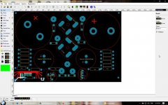
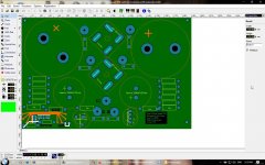
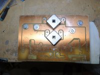
Finished LAYOUT WORK and PCB ready to solder
Hi Guys..
Sunday evening 5:25 PM, PCB for the PSU is almost finished,
Lsst night at midnight I got Tired and the PCB LAYOUT was far from finished, so I decidet to postpone to this morning..
Got up at 6:30 made coffee for me and my wife, had breakfast almost american, because of , wife made scramled eggs..
After that took another nab till about 9:30 am and then I went to finish Layout, made the film to make that PCB and then it was already noon, so we had lunch. Beef Thai Style with Rice and some vegetable.. Very delicous as always.
After that I rechecked the layout once more and after that I made the PCB and it was finished, first thing I did made clearance check and then drilled it..
Next PCB I need to develope the Positive film a few seconds longer but looking at it, I can say its ok for a sunday job.
OK Of course I made a few pics. and with a unprocessed board, this means drilled but not cleaned yet .. So just to give you an Idea how it looks like when its finished, I also mounted the most important components on it..Still a lot of work to be done..
Fan Control I will insert when the Board is ready to solder.. I decidet not to imply the Speaker Protection on this one.. Get it separate, may on the next project if there is one.
Guys have fun... and take alook a the pics..
Thanks for Reading
Enjoy Sunday as I do..
Cheers Chris
Hi Guys
Now drawing the Artwork for the Powersupply PCB.
I'm on it for about 4 hours already because was in need to measure the involved components and safe them to the Art Program, so that these parts will fit on the PCB afterwards.
Regards Chris
Hi Guys..
Sunday evening 5:25 PM, PCB for the PSU is almost finished,
Lsst night at midnight I got Tired and the PCB LAYOUT was far from finished, so I decidet to postpone to this morning..
Got up at 6:30 made coffee for me and my wife, had breakfast almost american, because of , wife made scramled eggs..
After that took another nab till about 9:30 am and then I went to finish Layout, made the film to make that PCB and then it was already noon, so we had lunch. Beef Thai Style with Rice and some vegetable.. Very delicous as always.
After that I rechecked the layout once more and after that I made the PCB and it was finished, first thing I did made clearance check and then drilled it..
Next PCB I need to develope the Positive film a few seconds longer but looking at it, I can say its ok for a sunday job.
OK Of course I made a few pics. and with a unprocessed board, this means drilled but not cleaned yet .. So just to give you an Idea how it looks like when its finished, I also mounted the most important components on it..Still a lot of work to be done..
Fan Control I will insert when the Board is ready to solder.. I decidet not to imply the Speaker Protection on this one.. Get it separate, may on the next project if there is one.
Guys have fun... and take alook a the pics..
Thanks for Reading
Enjoy Sunday as I do..
Cheers Chris
Attachments
-
 8. Layout ComponentsTop side.jpg147.3 KB · Views: 64
 -
 7. Layout PSU Top side.jpg157.8 KB · Views: 63
 -
 6. Layout PSU Bottom side.jpg156.2 KB · Views: 91
 -
 5.PCB actuall PSU.jpg202 KB · Views: 96
 -
 4.PCB Checking spaces Borrom Side.jpg198.7 KB · Views: 85
 -
 3. PCB Checking spaces.jpg179.3 KB · Views: 226
 -
 2. PCB Drilled Bottom Side.jpg219.5 KB · Views: 225
 -
 1. Drilled Top Sise.jpg254.7 KB · Views: 225
Last edited:
Thanks for you input. It's not a problem of CLASS A or HEAT..
I have several Class A, even 2 which Nelson Pass designed. Still have one of them, the A100 Forte Audio.. The Threshold I sold in the late 90..
I want to go SINGLE END, nothing Pushpull. Sound differs just too much.
The one I placed the cirquit, sorry not working on that one,, that one already works without flaw. I'm working on a transistor Version Single End. Transistor from input to output..Also that one works without a flaw.
Never mind the Heat I can take care of that.
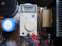
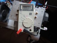
I have to much noise coming from Powersupply and that's what I'm working on.. So what I do now is creating a adequate Powersupply which can deliver steady 5.4 Amps at +- 42 Volts. The amp works fantastic.. heat is on 68C degrees, that's nothing if I compare that one to the other ones I have.,. there you can cook eggs on them ..and not one broke till now..
As soon I'm finish testing the PSU, its running but not that good as I thought, so I have to redesign it one more time, and that I will do this week. So next weekend *PCB I can only make on Weekend, as any other day I do not have enough time to make them proper.*
Anyway, your Input is appreciated..I soon will know if the new design works.. And believe me, I will not stop, before it works the way I want it to work.. If you tired of reading, just let me know.. and I will not post anything anymore.. I registered in 2012 and first time I made post here was one month ago..
Thanks for your comment one more time.
Regards
Chris
I have several Class A, even 2 which Nelson Pass designed. Still have one of them, the A100 Forte Audio.. The Threshold I sold in the late 90..
I want to go SINGLE END, nothing Pushpull. Sound differs just too much.
The one I placed the cirquit, sorry not working on that one,, that one already works without flaw. I'm working on a transistor Version Single End. Transistor from input to output..Also that one works without a flaw.
Never mind the Heat I can take care of that.
I have to much noise coming from Powersupply and that's what I'm working on.. So what I do now is creating a adequate Powersupply which can deliver steady 5.4 Amps at +- 42 Volts. The amp works fantastic.. heat is on 68C degrees, that's nothing if I compare that one to the other ones I have.,. there you can cook eggs on them ..and not one broke till now..
As soon I'm finish testing the PSU, its running but not that good as I thought, so I have to redesign it one more time, and that I will do this week. So next weekend *PCB I can only make on Weekend, as any other day I do not have enough time to make them proper.*
Anyway, your Input is appreciated..I soon will know if the new design works.. And believe me, I will not stop, before it works the way I want it to work.. If you tired of reading, just let me know.. and I will not post anything anymore.. I registered in 2012 and first time I made post here was one month ago..
Thanks for your comment one more time.
Regards
Chris
Last edited:
Thanks for your Input.. If everything goes wrong, and I can't manage to create a Powersupply which can handle the current, then of course I will consider to Buy an SMPS..
Is this you in the Avatar? What kind of Guitar, Fender Stratocaster? I got a Les Paul .. but I do not play anymore.. hands don't move anymore or too slow.. too old for that,. Stop to play ten years ago..
But the Gibson I keep..
Regards
Chris
Is this you in the Avatar? What kind of Guitar, Fender Stratocaster? I got a Les Paul .. but I do not play anymore.. hands don't move anymore or too slow.. too old for that,. Stop to play ten years ago..
But the Gibson I keep..
Regards
Chris
Thanks for your Input.. If everything goes wrong, and I can't manage to create a Powersupply which can handle the current, then of course I will consider to Buy an SMPS..
Is this you in the Avatar? What kind of Guitar, Fender Stratocaster? I got a Les Paul .. but I do not play anymore.. hands don't move anymore or too slow.. too old for that,. Stop to play ten years ago..
But the Gibson I keep..
Regards
Chris
Thats an old picture of me.
Its a Peavey Patriot which was expensive when I got it about 25 years ago.
Still plays well. For some reason I stopped playing about 10 years ago after being keen for 30 years. Tend to get bogged down designing electronics and software these days to sell.
I always fancied a Gibson but out of my price range.
I just finished building a couple of JLH1996, the newer version of the 69.
I used an SMPS for that but only a 20 watt supply.
Its very good with no hum.
Thanks for your answer ..
The Class A doesn't run away .. it lays on the table with it's now PSU.. there is no need for me to hurry. The one I made last week and tested yesterday got some design errors..
So my bad. I failed to make it better.. no problem..here the edge data
Line in Swiss is 220V AC
Toroid Transformer with 35-35 Volts free running two coils.
When the Amp is switched on it draws 5.4Ampere Current, per SIDE.
Power-supply is used only for one CHANNEL
Voltage drops to 42 + and 42- Volts.
I think 500VAC of the transformer should be enough at least .. and usually it will stay that way for hours..
I use per channel, two 200Volts 25 Ampere Bridges and 22'000uf Filter Capacitors some bypass, that's why the new PCB to extend this with some noise & Ripple killer.
I got a ripple of about 400mv P-P = Output voltage not loaded +-48 Volts with this config .but this is too much I want that down to 20mv.. at max..
The thing is I can measure this*HUM* but not actually hear that there is HUM NOISE..,
I use I.Q. Series Loudspeaker on this amp with and this are quite fast response.. cant tell the accurate SPL of them.. Thought it's something at 92 DB,.. Can't hear any hum or noise on them.. also not on the Shelf Speaker B&W if I use this ones..
But as I said I can measure it.and from my point of view it is too high.
Thanks again..
Regards
Chris
Attachments
Thanks for your answer ..
The Class A doesn't run away .. it lays on the table with it's now PSU.. there is no need for me to hurry. The one I made last week and tested yesterday got some design errors..
Chris
No the Class A will not run away..
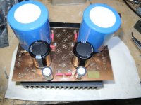
Here some update on this project..
Here it's very important to understand what I wish to achieve..
I wish to achieve a CLASS A SINGLE END AMPLIFIER, using regular Bipolar Transistor at the output and this one as SINGLE ENDED.
I have started this project long time before I started to write here.. That I write here, is not that I want to show off or anything else. I was asked to from someone and that's the only reason that I write write here.. I want to keep my promise to that person.
In the past months I have designed about 6 Versions of CLASS A SINGLE END AMPLIFIER Started out with the OP37Version with one Transistor..
BTW I'm in full knowledge that the OP AMP isn't CLASS A. But the Stage afterwards it is..
Then someone told me - yes as little parts as possible - Exactly my style - and keep the OP amp out.. I actually do not agree, because OP AMPS are very reliable devices and there are some very good sounding ones.. only that those do not have enough power to drive Loudspeaker,, not talking about the all in ones.. those ones forget about..
when I started to write, I had two working Amps Here (not talking about all the other amps I have made before.)with NE5534 and OP37 output MJL4281.. Please understand, there is only 1 IC output with Rail voltage +- 24 volts *Max is 22* delivering 10.5Volts RMS. This driven with a Rail on the Output Transistor of +- 37Volts with a RE Resistor 10 Ohm delivers 10.2 Volts RMS before clipping and distortion under .5% So this are
13.5 Watts @ 8Ohm or Output before clipping and distortion under 0.5% @4 Ohm is 9.2 Volts RMS which then is 22 Watts / nice and clear sound. Very linear from 10 - 100khz within .5db. at least on my digital Oscilloscope.
Everything below this line has nothing to do with the Amp above.
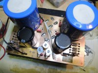
That's why I created a Transistor Version of it using the same output but input changed to BC556, drive Transistor is variable BD139 or MJE340 or SD669, BD139 has proven itself to give the best respond in every aspect detail & nuance, but compare to the other two transistors it needs to be fitted against the Heat-sink.. Lower right in the Picture you can see. I use pressure from a Flexible Acrylic to push the transistor against the Heat/sink.
What has happen is, DC output run away so I designed a double DC LOCK using two Transistors which compare Input Ground Output and also V+& V- between output and Input which does not alter the sound nor does it function as negative Feedback. but just controls DC Voltage of the first Transistor by comparing the DC Voltage to .773Volt which can be measured at the Base of BC556 when Output is 0.000Volts..Removing the coupling resistors will not change the sound, but DC output will variate.
Then also I installed a OP amp as *PID* which does the same thing but for the real small voltages and correcting them fast. this is only for Startup, so the Amp will be ready to use within 2 seconds after it has been powered on.this OP Amp can be removed, and the Amplifier will still work same as with installed OP Amp.. the only thing is DC Volts at the output needs to be adjusted again for use without OP amp.. Startup is somewhat slower as well as correction for DC
All this has had also negative sides.. the biggest was NOISE and HUM from Power Supply. First I used huge 68000uf Capacitors with only one Bride to get rid of .. nothing changed much, then I added a high pass filter into the adjustment line for DC and this helped.. Cross Frequency is .005 hz this removed NOISE and HUM so that it could not be heard in the loudspeaker while open or shunt to ground input. Everything quiet.. Then I used REW to check Noise/Signal Ratio and also distortion and you can see in the pictures, that THD was at.045 at Full Load. 2nd to 9th Harmonics were even better..
The Transistor version is running on +- 42 Volts with 5.5 Ampere Idle or BIAS. The Transistor version has a Bandwidth 10hz - 57Khz within .2db 100k -3db this with THD of .045%.
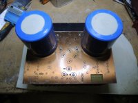
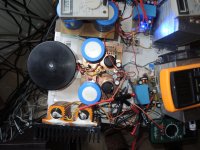
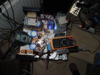
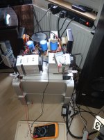
So I designed a new Power-supply in my free time at my Restaurant - as because of Corona we have less Customers, but we need be there.. so this Time I designed the new PSU. The PCB I made Sunday Morning and also I assembled it on Sunday.. It took all my time I usually rest until midnight. because I was also Assembling. And then Concentration went down and I inserted one of the CORE CAPACITORS the wrong way around.. this cost me 2x 25Amp/200Volt bridges they got up in smoke with big bang. Also it cost me a lot of time to change the Bridges, cleaning the Board..I know it's a shame to do things like that but, I think my concentration wasn't good anymore and I tried to get that finished on Sunday, but it did not happen.. It has happen today after 8 hours of work at my Restaurant.. I sat down and controlled the new PCB from the Power supply.. Now its done.. Works fantastic also the Automated Fan control.. needs a minor speed adjustment because temp goes up to 81.7C I would like to have it at max while outside of the Box at 60C.. if it goes up to80 or 08 in the BOX never mind,..
The left amp is the Transistor Amp Green AMP METER is for LEFT, Yellow Voltmeter is for LEFT meaning Transistor Amp. Transistor amp has Orange LED to indicate running.. the IC AMP has BLUE LED..
Sorry for the Long Post.,. the next part will be getting the Final Amps into the BOX. those you see in the pictures are just Prototypes.. Into the box there comes the Transistorized version.
Check out the Pics..
Listening to Single End compare to Push pull or Single End with Current Transistors, differs and not just a little bit..
Comparing the IC CLASS A with the Transistor CLASS A they are almost similar. The transistor has more DRIVE, PUSH and is more accurate..
Of course in the coming days I will measure NOISE/Signal Ratio and Distortion one more time..
Thanks For Reading.
Next Post will be getting the BOX and old MAC PRO G5 ready to become a Class A Amp.
BTW it's 3 am here in Switzerland.. and I have to get up at 6:30
Regards Chris
Attachments
-
 8.Loudspeaker output_s.jpg158.4 KB · Views: 66
 -
 6. Amp Right Cannel_s.jpg216.6 KB · Views: 57
 -
 5. DC outpu Right Channel_s.jpg133.2 KB · Views: 53
 -
 4.DC Ouput_s.jpg181.3 KB · Views: 57
 -
 3.Ampere and Heat_s.jpg196.5 KB · Views: 61
 -
 2. Powersupply_s.jpg208.2 KB · Views: 61
 -
 1.Class A Amps_s.jpg205.7 KB · Views: 236
 -
 01.20.PCB Powersupply_s.jpg206.9 KB · Views: 239
 -
 01.2.PCB Powersupply_s.jpg147.5 KB · Views: 232
 -
 01.0PCB Powersupply_s.jpg154.6 KB · Views: 257
Last edited:
Output is 13.8Volts RMS before Clipping and .045% THD this equals 23 WattsNo the Class A will not run away..
The Transistor version is running on +- 42 Volts with 5.5 Ampere Idle or BIAS. The Transistor version has a Bandwidth 10hz - 57Khz within .2db 100k -3db this with THD of .045%.
Regards Chris
@8Ohm
and I get 12.2Volts RMS before Clipping and also .06% THD @4Ohms
this equals 38 Watts.
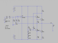
Circuit Class A Single End Amplifier
Hi everyone
Here is the Circuit to the Amplifier we are talking for the past weeks..The transistorized one.
This one is the basic Cirquit I use for several years already with Current source Transistor amplifiers, and now with Single End Class A..
There were many changes to the Cirquit prior to the single end. The real change is that there is no Current Source, as the Emmiter Resistor is the rule for Current flow..
Also for Output level, distortion and other things and not last Sound Quality.
But to get a reliable good Amplifier there is some add ons of which I will place the circuit following this one. This amplifier as you see it in the circuit will work just fine untill it gets hot.. all transistors except input need to be on the same HEATSINK. It will work from DC Rail +- 35 Volts up to +- 42 volts.
Operating it with these Voltage, a DC LOCK from input to output is a need or a PID.
Both of this I place the Circuits here as well.
As last I will place the PSU Circuit which I designed last week,, But even it works good it needs a few corrections. and when done I will also place that one here.
All files are PDF .. also the layouts..Now my layouts requesting special heat sinks.. but still you can use this with regular heatsink if you like too, by just designing the OUTPUT transisitors one more time. Any Input is welcome.
Layouts will follow in a few days as I have to recheck against the one is under test.
I forgot, the Emitter RESISTOR in the Class A Circuit pdf is 7.5 ohm 400WATTS. this one gets really hot.
Thanks for Reading..
Regards Chris
Attachments
-
 ScreenShot029.jpg326 KB · Views: 89
 -
 ScreenShot028.jpg319 KB · Views: 97
 -
PID Control Class Amplifier Single End.pdf226.6 KB · Views: 67
-
DC LOCK Circuit for CLass A Amplifier.pdf260.4 KB · Views: 67
-
Single End Class a Transistor Amplifier 3 stage.pdf256.4 KB · Views: 99
-
 ScreenShot033.jpg326 KB · Views: 59
 -
 ScreenShot030.jpg325.9 KB · Views: 59
Last edited:
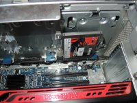
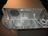
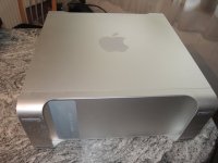
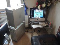
POWER MAC G5 Case - Not Build yet
Actually the Class A Amp should be in its case by now already..
May you have noticed from the pictures that I have a flair to use Power MAC G5 Cases..
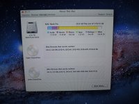
Two months back I could buy one, exactly for that reason to use as Class A Amplifier Case. Now last week when I was going to remove all the computer components from the box, I suddenly was surprised about the inside, it looked somewhat different from what I have seen before.
1. There are 2 CD/DVD drives
2. There is a High Power Graphics ATI 5770 Card in it
3. There are are two Memory Add On Banks in with *for that time as it was build in 2006* 667Mhz High Speed Memory installed.. totals of 5 GB..
4. The Graphic Card has two MAC Video / TV outputs besides the DVI
5. Hard drives where missing.. but also, instead of only 2 there are three Hard drive Slots.
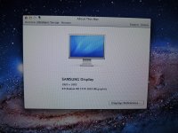
So before removing anything I connected the big Samsung Screen , Keyboard and Mouse and pushed the Power button. The next what I knew is that the Graphic card has MAC's Graphic Card Virus..As we could see it in the Mac Pro Laptops from 2010 on-wards as they used I7 Chips with ATI Combined.. * I have three of them* each of them Broke down with the Same Virus.. Graphic Chip ATI Failure.. Bad solder connections to and from and also within the ATI Chip.. Produced by AMD = Another Misty Device
But I also know how to repair this problem at least for sometime * Re soldering is the Trick* using lots of non corrosive solder fluid and a hot air gun..or a Top and Bottom heated oven with 200 Degrees for 2 Minutes..Protect the Part which should not be heated to extremely with Aluminum Foil. Errors like that is the death of the Graphics Card anyway, os there is nothing to lose.. if it fails.. If would have failed the CLASS A would be in there by now and you could see the documentation.. I hope next Sunday you will see this..
After dissembling and reassembling that Graphic ATI Card, with 1 GB Memory, plugged it in and the G5 Started up..
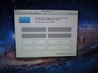
Opened the DVD to install Leopard 10.5.7 but the computer refused..
This Operating System does not install on this Hardware -- or Similar..
So what to do..?
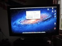
Took a copy of my Laptop SSD Drive with Snow Lion 10.7.5 plugged it into the drive bay and pushed the Power button..
And here we go.. Check out the pics.. that is the reason that I don't have a case right now to build that Class A..
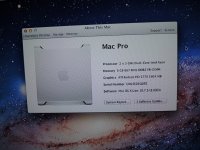
There is a word,. Never Change a Running System but for me I have another one.. Never Destroy a Running System..
Found a G5 on the internet here in Swiss which I can buy soon for small money to take the case.. where I'm sure that it is not a DUAL XEON..meaning Intel Based MAC.. those Ones I keep.
this one has Optical in out so I can make it to Media Server as I use Optical for Connections as much I can.. The Imacs I got do not have Optical in/out..
Speaking of PC and MAC, I'm not what you call a MAC lover.. Using PC's more that MAC but in that case MAC is more advanced than Billys W10 or what ever he produced..
Lion 10.7.5 which was released in 2011 / 2012 as far as I know is backward compatible with a Computer they build in 2006.. It boot up and runs without errors, except the MAC does not actually like the Advanced APPLE Keyboard of my IMAC .. but it takes a regular PC KEYBOARD.. what world.
If everything goes the way I plan, then I should be in possession of another G5 on the 19th this month.. then we will start to build that CLASS A into that G5, only to keep the *line*
Check out the pics.
But after that I will need a lot of guidance, because I'm going to Create this CLASS A with TUBE INPUT and Transistor Single End output.. So Guys I will need your help on that coming one..
Thanks In Advance.
Chris
Actually the Class A Amp should be in its case by now already..
May you have noticed from the pictures that I have a flair to use Power MAC G5 Cases..
Two months back I could buy one, exactly for that reason to use as Class A Amplifier Case. Now last week when I was going to remove all the computer components from the box, I suddenly was surprised about the inside, it looked somewhat different from what I have seen before.
1. There are 2 CD/DVD drives
2. There is a High Power Graphics ATI 5770 Card in it
3. There are are two Memory Add On Banks in with *for that time as it was build in 2006* 667Mhz High Speed Memory installed.. totals of 5 GB..
4. The Graphic Card has two MAC Video / TV outputs besides the DVI
5. Hard drives where missing.. but also, instead of only 2 there are three Hard drive Slots.
So before removing anything I connected the big Samsung Screen , Keyboard and Mouse and pushed the Power button. The next what I knew is that the Graphic card has MAC's Graphic Card Virus..As we could see it in the Mac Pro Laptops from 2010 on-wards as they used I7 Chips with ATI Combined.. * I have three of them* each of them Broke down with the Same Virus.. Graphic Chip ATI Failure.. Bad solder connections to and from and also within the ATI Chip.. Produced by AMD = Another Misty Device
But I also know how to repair this problem at least for sometime * Re soldering is the Trick* using lots of non corrosive solder fluid and a hot air gun..or a Top and Bottom heated oven with 200 Degrees for 2 Minutes..Protect the Part which should not be heated to extremely with Aluminum Foil. Errors like that is the death of the Graphics Card anyway, os there is nothing to lose.. if it fails.. If would have failed the CLASS A would be in there by now and you could see the documentation.. I hope next Sunday you will see this..
After dissembling and reassembling that Graphic ATI Card, with 1 GB Memory, plugged it in and the G5 Started up..
Opened the DVD to install Leopard 10.5.7 but the computer refused..
This Operating System does not install on this Hardware -- or Similar..
So what to do..?
Took a copy of my Laptop SSD Drive with Snow Lion 10.7.5 plugged it into the drive bay and pushed the Power button..
And here we go.. Check out the pics.. that is the reason that I don't have a case right now to build that Class A..
There is a word,. Never Change a Running System but for me I have another one.. Never Destroy a Running System..
Found a G5 on the internet here in Swiss which I can buy soon for small money to take the case.. where I'm sure that it is not a DUAL XEON..meaning Intel Based MAC.. those Ones I keep.
this one has Optical in out so I can make it to Media Server as I use Optical for Connections as much I can.. The Imacs I got do not have Optical in/out..
Speaking of PC and MAC, I'm not what you call a MAC lover.. Using PC's more that MAC but in that case MAC is more advanced than Billys W10 or what ever he produced..
Lion 10.7.5 which was released in 2011 / 2012 as far as I know is backward compatible with a Computer they build in 2006.. It boot up and runs without errors, except the MAC does not actually like the Advanced APPLE Keyboard of my IMAC .. but it takes a regular PC KEYBOARD.. what world.
If everything goes the way I plan, then I should be in possession of another G5 on the 19th this month.. then we will start to build that CLASS A into that G5, only to keep the *line*
Check out the pics.
But after that I will need a lot of guidance, because I'm going to Create this CLASS A with TUBE INPUT and Transistor Single End output.. So Guys I will need your help on that coming one..
Thanks In Advance.
Chris
Attachments
-
 9. SSD NOW.jpg209.1 KB · Views: 76
 -
 8.Specs Mac_s.jpg255.9 KB · Views: 39
 -
 7. Specs Mac_s.jpg228 KB · Views: 39
 -
 6.Specs Mac_s.jpg268.9 KB · Views: 52
 -
 5.Specs Mac_s.jpg270.1 KB · Views: 60
 -
 4.Desktop Mac_s.jpg179.2 KB · Views: 72
 -
 3.Mac_s.jpg205.3 KB · Views: 76
 -
 2.Mac_s.jpg243.1 KB · Views: 73
 -
 1.Mac_s.jpg156.4 KB · Views: 98
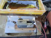
Finally I managed to buy this case, can pick it up next monday evening. In the meantime I'm still working on that circuit in sight of power input / power output / distortion that its in somekind spec, without losing quality of sound.
Final Circuit as well as the final build I hope to have ready within next week.
I have to admit that in the meantime because of poor fixing of the PCB against the hetsink one channel blew up.. Output transistor shorted out because of a short between Emitter Resistor and Heatsink.. This I have corrected now.. But exactly for this is long time testing.
Also this had happen, after I moved the AMP - of course the Amp is not in a case now.. And because of the PCB was only fixed by the pressure Aluminum Plate of Powertransistors it made that short.. My bad, its not a fail of the circuit.
In the meantime I have fixed it, to prevent any furthere shorts. I also have to say that sometime I turn or move the AMP upside down without switching ot off to get REAL TIME Measurements. Withouth Investments no benefits ansd benefist in this case means, a good quality Amplifier. I'm not satified with "OK that's good enough" Only the Best I can do is good enough.
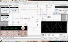
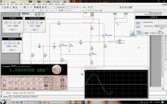
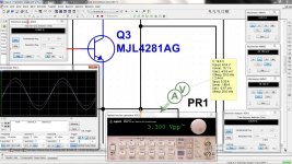
Here a few Screenshots of this Amp while Simulating Power vs Frequency Bandwith and Distortion. I made more Pictures up to 100Khz but i can only place ten of them.. Rest folows later. This what you see is the newly calculated version without SERVO control nor does it have a DC-LOCK cirquit. Also RE has been increased to 10Ohm insteade of 7.5 Ohm at a Rail voltage of 42 Volt. So now the Amp is drawing around 4Ampere idle Current. Checkout the pictures Simulation of actual ruuning Amp. It is already build, I'm to old to waste time
Tomorrow I will make the same on the REAL Amplifier so you can compare.
Regards and enjoy Weekend
Chris
Final Circuit as well as the final build I hope to have ready within next week.
I have to admit that in the meantime because of poor fixing of the PCB against the hetsink one channel blew up.. Output transistor shorted out because of a short between Emitter Resistor and Heatsink.. This I have corrected now.. But exactly for this is long time testing.
Also this had happen, after I moved the AMP - of course the Amp is not in a case now.. And because of the PCB was only fixed by the pressure Aluminum Plate of Powertransistors it made that short.. My bad, its not a fail of the circuit.
In the meantime I have fixed it, to prevent any furthere shorts. I also have to say that sometime I turn or move the AMP upside down without switching ot off to get REAL TIME Measurements. Withouth Investments no benefits ansd benefist in this case means, a good quality Amplifier. I'm not satified with "OK that's good enough" Only the Best I can do is good enough.
Here a few Screenshots of this Amp while Simulating Power vs Frequency Bandwith and Distortion. I made more Pictures up to 100Khz but i can only place ten of them.. Rest folows later. This what you see is the newly calculated version without SERVO control nor does it have a DC-LOCK cirquit. Also RE has been increased to 10Ohm insteade of 7.5 Ohm at a Rail voltage of 42 Volt. So now the Amp is drawing around 4Ampere idle Current. Checkout the pictures Simulation of actual ruuning Amp. It is already build, I'm to old to waste time
Tomorrow I will make the same on the REAL Amplifier so you can compare.
Regards and enjoy Weekend
Chris
Attachments
-
 10. Square 20Khz 2Watts into 8Ohm.jpg791.2 KB · Views: 36
 -
 9.Square 1Khz -2Watt.jpg785.9 KB · Views: 37
 -
 8. Square 1khz-fl.jpg785.9 KB · Views: 41
 -
 7. Sine 50khz-fl less 1percent disto.jpg800 KB · Views: 32
 -
 6. sine 50khz fl-1.8 disto.jpg803 KB · Views: 44
 -
 5. Sine 50Khz -1Watt into 8ohm.jpg801.8 KB · Views: 36
 -
 4. Sine 20khz -fl with less than 1percent disto.jpg788.3 KB · Views: 43
 -
 3. Sine 20Khz 1Watt.jpg799.5 KB · Views: 40
 -
 2. Sine 1khz-fl -less than 1percent disto.jpg798 KB · Views: 69
 -
 1. Sine 1Khz into 8 ohm.jpg803.1 KB · Views: 82
Last edited:
I can see the Finish Line of this Build is coming closer..
So Amps have been tested, latest Layout BTW Version 5 is ready to Fabricate the PCB's used for this Amp. Circuit has changed a little bit as well, it's available with and without DC SERVO. The layout is on PCB, but it can be used or not, talking about the SERVO DC Control Amplifier, which safes the Class A from spreading DC Voltages higher than 5 mv to the Loudspeaker.. if not used then it will be +- 25mv with signal and about 9mv without signal..
BTW I got that Case last Sunday, but couldn't work on it, as there is many different things to take care of.. My BMW was striking on me for a few Times, so I had to get another Car to take care of our business and also ordering the Spare Parts for the BMW 530XI..
And I made another two PCB's which turned out not actually good to look at, but fortunately I found my mistakes while edging the PCB.
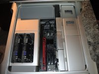
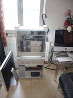
anyway I think I will be able to rip out everything of the MAC G5 you can see in the Picture..the top one.. the lower One I will use as a Media server for testing.
The left side Amp you can see in the picture will be the Amp going into that G5 BOX..
The other side, the OP stage Class A Single End will find it's way into the shelf, with other Prototypes..into the Case, there 2 Brand New never used Amps will be put into.. also Brand New Transformers and also Brand New Power-supplies. @ Schmitz77, yeah and the Toroids will be stacked,.
Regards
Chris
So Amps have been tested, latest Layout BTW Version 5 is ready to Fabricate the PCB's used for this Amp. Circuit has changed a little bit as well, it's available with and without DC SERVO. The layout is on PCB, but it can be used or not, talking about the SERVO DC Control Amplifier, which safes the Class A from spreading DC Voltages higher than 5 mv to the Loudspeaker.. if not used then it will be +- 25mv with signal and about 9mv without signal..
BTW I got that Case last Sunday, but couldn't work on it, as there is many different things to take care of.. My BMW was striking on me for a few Times, so I had to get another Car to take care of our business and also ordering the Spare Parts for the BMW 530XI..
And I made another two PCB's which turned out not actually good to look at, but fortunately I found my mistakes while edging the PCB.
anyway I think I will be able to rip out everything of the MAC G5 you can see in the Picture..the top one.. the lower One I will use as a Media server for testing.
The left side Amp you can see in the picture will be the Amp going into that G5 BOX..
The other side, the OP stage Class A Single End will find it's way into the shelf, with other Prototypes..into the Case, there 2 Brand New never used Amps will be put into.. also Brand New Transformers and also Brand New Power-supplies. @ Schmitz77, yeah and the Toroids will be stacked,.
Regards
Chris
Attachments
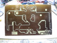
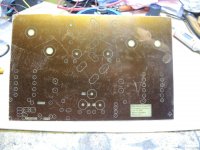
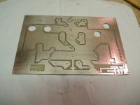
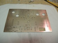
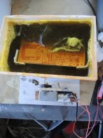
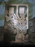
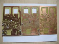
Edging the Final PCB's
So, The Final Circuit now has been completed as well as the latest PCB Version.
I would like to say that all what you see here is Hand made. For edging I made small little Motor driven shaking machine. Of course it's outside the Working room at fresh air.. on a separate Table, where it doesn't matter if some Ferro 3 Chloride is spilled.. To keep temperature of the Edging fluid it will be changed about all 5 - 10 minutes with new warmed up fluid. Also this shaking construction with a motor helps to keep the fluid moving.. So it edges a little bit faster.. Outcome is OK I need wide Tracks because or high Ampere design. The smallest of the tracks is 1mm in width and the widest 6.5 to withstand 25 Ampere Current in the case of a short.Also a few Security Tracks has been inserted to the Collector and Emitter Tracks as well. So if there is to be a short which is going to kill the tracks for whatever reason it will be only small damage..
OK prior to this PCB's and because of not being satisfied with it, there is number or Revision 5.
At left is Revision 3 which is actually to one you see for quite some time in pictures while testing, and it kept it's promises of good sound and stability.
But I changed some of the circuit, removing DC Lock Circuit because of being to slow in reacting to the rest of the circuit, and I found a workaround with adding one resistor to the circuit and got the better results than with this DC LOCK.. May I the future I will add this one more time when I have tested it more than it is tested at present time.
Second picture on that white leaf of paper is Revision 4, and no explanation is needed.. Check the right upper edge and then you see why it didn't made it. also some other small things I had to change when I saw the PCB, I was actually not happy about it.. And on the right side, this one will sure have a good chance to be build into the BOX.. This afternoon when I come back from Work, I will make another two PCB's trying to get a more Sharp edging out of it.. Even there will be only on AMP with this, but serious Testing has been done, because once build it will not be changed anymore..
Check Out the Pictures.
Thanks for Watching.
Regards Chris
Attachments
Last edited:
- Home
- Design & Build
- Construction Tips
- Building a Class Amplifier from Scratch