@hpro,
Regarding the transformer, you're likely refering to the 'Audio Grade', with magnetic screening and other extras. Good stuff, glad you found what you were looking for.
Regarding the transformer, you're likely refering to the 'Audio Grade', with magnetic screening and other extras. Good stuff, glad you found what you were looking for.
Rewied Circuit Class A Positive Rail
Guys, because of waiting for the Second Transformer which is in overdue already 5 days, I modified the Cirquit *Modifications already were planned beforehand* at the third Transistor by changing the Rail voltage of the third Transistor *BD139-16* from a Negative Rail Resistor to a Positive one..
Reasons for change is, that the Cirquit with the Negative Rail Resistor of Transistor number 3 is actually "Faulty" in the means of the collector of that Transistor isn't in use.
The cirquit is fully functional from 10Hz to 100Khz +- .2db so only Base Emitter is in use on that circuit.. But actually goes up to 380Khz - 3db
Now I changed this by moving the Rail Resistor to V+ instead of V-.. specs are almost the same.. for me the first circuit *Rail Resistor V- * is better with lower THD..
But it's in my point of view not " Finished, using open collector/./
Check out the update of the Cirquit.. This is with RE10 Ohms which can be as low as 6.5 Ohms without modifications of other parts.. Adjusting DC out, which will be done with a few Turns.. If PID is used then NO Adjustmenst are needed..
PDF 1 is with 1khz and the second one is with 100Khz to compare you need to Enlarge the document to read the data at the output
Attachments
Last edited:
Just got note from Farnel, that the second Transformer should arrive today late afternoon..
BTW, now it's 3am in Swiss.,. so Restart of building the rest of that Class A Single End Amplifier, is in due shortly.
I hope by Sunday I'm able to have that amp in the BOX and wiring is done. Even I need to make a few PCB for PSU, but this depends how far I will be finish with Air-channeling the from Heat sinks to both sides of the BOX as soon the AMP have been screwed in. And then have to measure Noise of the FANS and may need to adjust Speed for Cooling it properly, or reduce speed because of noise of the Fans.. and, and, and..
And none of this could be done because of Transformer were on the road for almost 2 months.. weird but true..
Need your Advice on Placing Transformers
So, my last post was August 13th..
2nd.Transformer arrived the same day late in the afternoon.. But since Corona is spreading around like nothing else, and we have a Business which is very delicate to Corona News, I needed to take care closely to our Business, so that it won't go down the drain. I know it's for everyone exactly the same..
The Business is a Restaurant, and is very much depending on the news of Government and the associated Department, what kind of news and restrictions they invent each new week.. and most of them hurt our Business.
This, makes it very hard for me to get that Amp done more quickly.
Most Time consuming Factors are long delivery Times from Part suppliers, I waited over 2 Months for these two Transformers.
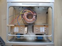
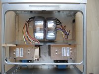
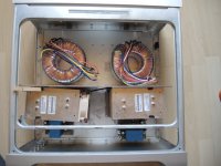
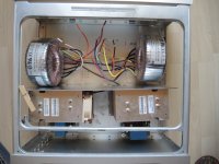
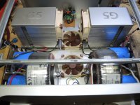
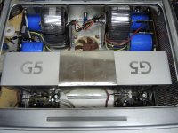
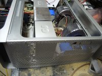
So today is Sunday, August 16th. Morning 09.20am in good old Switzerland, and I'm trying to figure out what would be the best way to place the Transformers in that Case so these Transformers would make the least possible interference which could be achieved. I have made some pics of my thoughts how Transformers could be placed,. What you think? Anyone in for a comments or advice, every advice comment is welcome. I personally have an Idea but I wish to know yours,.,
Again, as I wrote before, both amps which you see are only Placeholders. those can be moved as you like, if you think the way you place them are less difficult for Noise Hum Heat and centralized weight as well as the rest what comes with it..
On the Inner Backside of the AMP for width of 15 CM I like to place all Inputs and outputs then left and right to this the High Power Resistors with the Heatsinks.
I'm thankful for any input..
Front of the Case is the side with the AMPS..
Case inside Measures is length 45cm width 40 Cm and height is 20cm which can be used to place everything.
the pics are my Ideas and choices I see at present time to place the Transformers..
Please Note: for each Transformer there will also be a PSU with CRCLRCLR Caps are 33000uf 50 - 63 volts. Screwed to PCB diameter for caps are 66mm each PSU has 6 pieces 3 for + Rail and 3 for Minus Rail. Then also each PSU has Double Bridge, 400Volts 35 Ampere with Fan Steering on Board. Speaker Protection will be separated for the channels as and build placed separately.
Thanks in Advance.
Regards Chris
So, my last post was August 13th..
2nd.Transformer arrived the same day late in the afternoon.. But since Corona is spreading around like nothing else, and we have a Business which is very delicate to Corona News, I needed to take care closely to our Business, so that it won't go down the drain. I know it's for everyone exactly the same..
The Business is a Restaurant, and is very much depending on the news of Government and the associated Department, what kind of news and restrictions they invent each new week.. and most of them hurt our Business.
This, makes it very hard for me to get that Amp done more quickly.
Most Time consuming Factors are long delivery Times from Part suppliers, I waited over 2 Months for these two Transformers.
So today is Sunday, August 16th. Morning 09.20am in good old Switzerland, and I'm trying to figure out what would be the best way to place the Transformers in that Case so these Transformers would make the least possible interference which could be achieved. I have made some pics of my thoughts how Transformers could be placed,. What you think? Anyone in for a comments or advice, every advice comment is welcome. I personally have an Idea but I wish to know yours,.,
Again, as I wrote before, both amps which you see are only Placeholders. those can be moved as you like, if you think the way you place them are less difficult for Noise Hum Heat and centralized weight as well as the rest what comes with it..
On the Inner Backside of the AMP for width of 15 CM I like to place all Inputs and outputs then left and right to this the High Power Resistors with the Heatsinks.
I'm thankful for any input..
Front of the Case is the side with the AMPS..
Case inside Measures is length 45cm width 40 Cm and height is 20cm which can be used to place everything.
the pics are my Ideas and choices I see at present time to place the Transformers..
Please Note: for each Transformer there will also be a PSU with CRCLRCLR Caps are 33000uf 50 - 63 volts. Screwed to PCB diameter for caps are 66mm each PSU has 6 pieces 3 for + Rail and 3 for Minus Rail. Then also each PSU has Double Bridge, 400Volts 35 Ampere with Fan Steering on Board. Speaker Protection will be separated for the channels as and build placed separately.
Thanks in Advance.
Regards Chris
Attachments
New Arrangement in the BOX
Monday Morning 7:30 am in Swiss
Good Morning, day - night everyone,
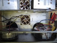
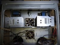
So after I placed these Pics of the Layout yesterday, I started to make Ventilation holes. and also cut out the space for Main Power Switch and Connector.. But then I had some kind of a new thought.
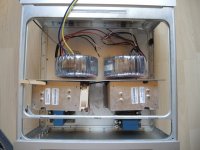
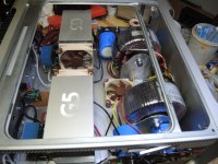
May if I turn all the Amps around to the Back-end of the case, so I would have shorter input and Output Paths from and to the board and all the heat is dissipated in one and the same place. especially the large Resistors would benefit from Ventilation of the Amps and Chassis fans
The pictures from yesterday, meant that the amps are in front of the Amplifier and the Transformers in the back,, but looking at this, does not really satisfied me..
So If I moved the Transformers to front, then possibility of Magnetic field to interfere with the sound Path are somewhat less, than the other way.
Also if there is a problem, I got more space to service the Amp, i.e. Exchanging Fuses, disconnecting in and outs of the Amps..without to have take all in pieces again..
So that way it looks much better and I got more Space for PSU as these will take quite some space with the Big Caps and Regulator Part, besides Soft-start and Fan Control Units.
Will find out later this Afternoon when I'm back from Business... now it won't take that long until the amps are in this box..
Now it will advance real fast for the rest of the work, even I have to make some PCB, for PSU - Fan Controls and Speaker Protection, but that's peanuts
Soon more of it..Today I will get all the drilling and cutouts done, later in the afternoon, so I can clean out the BOX of leftovers from Cutting and drilling.
Also need to construct four holding angles for the transformers, because each of them weights over 6Kilogramm.. And I do not want to make holes into the Front of the AMP BOX except for the Power Switch.
Then mounting the BIG Resistors at the back,. getting Speaker Ports and Input Jacks screwed in, and I guess when I'm finish it will be night time here in Swiss.
Enjoy the day
Enjoy the new Week Start
Regards
Hpro
Monday Morning 7:30 am in Swiss
Good Morning, day - night everyone,
So after I placed these Pics of the Layout yesterday, I started to make Ventilation holes. and also cut out the space for Main Power Switch and Connector.. But then I had some kind of a new thought.
May if I turn all the Amps around to the Back-end of the case, so I would have shorter input and Output Paths from and to the board and all the heat is dissipated in one and the same place. especially the large Resistors would benefit from Ventilation of the Amps and Chassis fans
The pictures from yesterday, meant that the amps are in front of the Amplifier and the Transformers in the back,, but looking at this, does not really satisfied me..
So If I moved the Transformers to front, then possibility of Magnetic field to interfere with the sound Path are somewhat less, than the other way.
Also if there is a problem, I got more space to service the Amp, i.e. Exchanging Fuses, disconnecting in and outs of the Amps..without to have take all in pieces again..
So that way it looks much better and I got more Space for PSU as these will take quite some space with the Big Caps and Regulator Part, besides Soft-start and Fan Control Units.
Will find out later this Afternoon when I'm back from Business... now it won't take that long until the amps are in this box..
Now it will advance real fast for the rest of the work, even I have to make some PCB, for PSU - Fan Controls and Speaker Protection, but that's peanuts
Soon more of it..Today I will get all the drilling and cutouts done, later in the afternoon, so I can clean out the BOX of leftovers from Cutting and drilling.
Also need to construct four holding angles for the transformers, because each of them weights over 6Kilogramm.. And I do not want to make holes into the Front of the AMP BOX except for the Power Switch.
Then mounting the BIG Resistors at the back,. getting Speaker Ports and Input Jacks screwed in, and I guess when I'm finish it will be night time here in Swiss.
Enjoy the day
Enjoy the new Week Start
Regards
Hpro
Attachments
While Construction goes on
Hi.
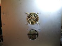
Hopefully the BOX can be "professionally painted tomorrow or Sunday, but only inside, outside it will stay Aluminum to match the other two Amps. Most drilling has been done, and Cutouts have been made. There is the placement for the OUTSIDE HEATSINKS which are not made yet, but tonight *Now it's almost 6pm Swiss Time* a Decision will be made tonight how Heatsinks will be mounted, so the Cutouts can be made, because the Sinks working in atwo step cooling way.. one part will be cooled from surrounding air, but inside a speed and heat controlled super low noise Fan will give the needet cooling..
Also Transformer stands have been made * not really finish but for testing them it's ok.
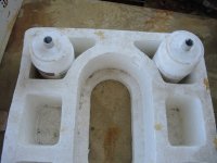
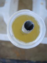
Then also Spacefillers for the Centerhole of Transformers also have been molded from Epoxy, but need to dry out for another 4 Days until those are usuable..
Powerswitch, Power Connector, Support Fan, AMPs have been test Mounted.. everything neat and clean..
As soon case has been painted, Main power Cables will be laid and fixed to the case, then Shielded with a half Pipe if possible.
Both Power Switches will be connected, the MAIN POWER and also Standby. Standby means in that way Cooling will work if needet but the AMPS will be shut down.
Then also Load Switches of the AMP will be mounted, those are controlling the Ouput Power as well as the HEAT of the AMP. Having something like 12Watts and 28 Watts in mind..This would equal heat between 50 - 80 degrees Celsius. I hope the amp will be ready to use by end of month.. So hang in there more Pictures will follow inclunding a full Specification under TEST LOADS and also small Video at real Time Run and RESPONSE, the way it really
is..
The only Bad is, the real sound can only be heard here in my home.. at least for Present time..I may have some surprise in mind for all you guys, but it's alot of work.. still
Here a glimpse while construction goes on, more and better Pics follow later..
Regards
Chris
Hi.
Hopefully the BOX can be "professionally painted tomorrow or Sunday, but only inside, outside it will stay Aluminum to match the other two Amps. Most drilling has been done, and Cutouts have been made. There is the placement for the OUTSIDE HEATSINKS which are not made yet, but tonight *Now it's almost 6pm Swiss Time* a Decision will be made tonight how Heatsinks will be mounted, so the Cutouts can be made, because the Sinks working in atwo step cooling way.. one part will be cooled from surrounding air, but inside a speed and heat controlled super low noise Fan will give the needet cooling..
Also Transformer stands have been made * not really finish but for testing them it's ok.
Then also Spacefillers for the Centerhole of Transformers also have been molded from Epoxy, but need to dry out for another 4 Days until those are usuable..
Powerswitch, Power Connector, Support Fan, AMPs have been test Mounted.. everything neat and clean..
As soon case has been painted, Main power Cables will be laid and fixed to the case, then Shielded with a half Pipe if possible.
Both Power Switches will be connected, the MAIN POWER and also Standby. Standby means in that way Cooling will work if needet but the AMPS will be shut down.
Then also Load Switches of the AMP will be mounted, those are controlling the Ouput Power as well as the HEAT of the AMP. Having something like 12Watts and 28 Watts in mind..This would equal heat between 50 - 80 degrees Celsius. I hope the amp will be ready to use by end of month.. So hang in there more Pictures will follow inclunding a full Specification under TEST LOADS and also small Video at real Time Run and RESPONSE, the way it really
is..
The only Bad is, the real sound can only be heard here in my home.. at least for Present time..I may have some surprise in mind for all you guys, but it's alot of work.. still
Here a glimpse while construction goes on, more and better Pics follow later..
Regards
Chris
Attachments
-
 10. Magnetic Field Shielding.jpg260.2 KB · Views: 104
 -
 9. Magnetic Field Shielding.jpg276.3 KB · Views: 100
 -
 8. Mounting Transformer with Stand and Spacefiller.jpg276 KB · Views: 111
 -
 7. Screwed AMP Inside.jpg269.3 KB · Views: 93
 -
 6. underneath Amp Case.jpg165.7 KB · Views: 87
 -
 5. Sample of Transformer Spacefiller.jpg303.6 KB · Views: 103
 -
 4. Sample of Transformer Spacefiller.jpg294.4 KB · Views: 108
 -
 3. Transformer Spacefiller Epoxy Resin - Waiting To Dryout.jpg279.7 KB · Views: 103
 -
 2. Transformer Spacefiller Epoxy Resin.jpg278.3 KB · Views: 95
 -
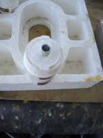 1. Transformer Spacefiller.jpg343.9 KB · Views: 98
Last edited:
Thought this takes too long, ? Me too I think the same, but unfortunately Some of the planned mounting inside the Box had to be changed because of Space Problems..
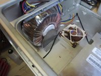
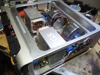
Then also self-made Silicone Buffers ( you can see in the Pictures from my last post) didn't work out the way it was intended, to keep vibrations of the two 750VAC Tororid Transformers out, so now I received Rubber Buffers, hoping that these do the job.. So all the fixing construction had to be changed. As the Transformers are hangup in a triangle Construction on both sides of the transformer.
Air cooling has been tested with the Noctua Fans.. and it's silent as never before.
More later this afternoon, with Pictures.. Inside color hasn't been made cause of bad Weather condition, the day when I were to go to spray that box to a neat and clean black inside. so I just keep it blank aluminum..
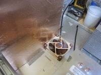
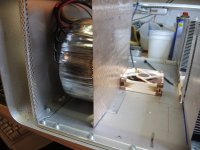
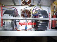
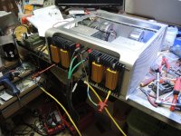
Took it a step further.. Mounted Transformers..
So Guys, as Promised, I had some spare time yesterday and this evening, now it's already 8:32pm.. So was working on the stands for the Transformers.. Positioned them and also made a TEST COVER for the Air Channel.
Picture are Self Explaining. everything will come out one more time to give it a nice finish, even it looks already good, but now the back is the next which must be made.
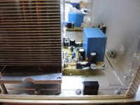
PSU will be placed for each Amp on the left and right outer-side, standing upwards.
So this delays the finish of the amp one more time, because I need to make new PCB's as the old one don't fit.. But never mind, have enough amps to listen too so better slow and good to excellent, then fast and ugly and bad..
Check out the pics..
Regards Chris
So Guys, as Promised, I had some spare time yesterday and this evening, now it's already 8:32pm.. So was working on the stands for the Transformers.. Positioned them and also made a TEST COVER for the Air Channel.
Picture are Self Explaining. everything will come out one more time to give it a nice finish, even it looks already good, but now the back is the next which must be made.
PSU will be placed for each Amp on the left and right outer-side, standing upwards.
So this delays the finish of the amp one more time, because I need to make new PCB's as the old one don't fit.. But never mind, have enough amps to listen too so better slow and good to excellent, then fast and ugly and bad..
Check out the pics..
Regards Chris
Attachments
-
 6. Powersitch.jpg104.6 KB · Views: 92
 -
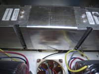 5. Cooling Amp.jpg180.2 KB · Views: 103
 -
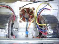 4. Transformer fittet.jpg772.1 KB · Views: 96
 -
 3. Transformer Fitting.jpg161.2 KB · Views: 100
 -
 2. Transformer Shock Absorbing.jpg164.2 KB · Views: 102
 -
 1. Transformer Antivibration.jpg145.6 KB · Views: 117
 -
 7. PSU and Regulation.jpg237.2 KB · Views: 103
Last edited:
Sorry only slow progress here.. Another waiting time
Guys,
I need to apologize here that not much progress shows on that build here..
Since it's a all new build, with different parts, and different thoughts, so choosing one way, if it works out that way then all is OK. If not then there I have to find a way around which will not downgrade the build in anyway.
Now here the problem is the cooling Heat sinks at the back for these two or four Emitter Resistors which are 200Watt per piece can not be mounted as originally thought.
There is not enough space between the Resistor and the Amplifier when the resistor is placed inside the box.. The original design was made that for each channel one or both of these RE are mounted against a HEAT SINK which is outside of the box - Please look here - https://www.diyaudio.com/forums/att...ass-amplifier-scratch-4-re-heatsink-psusw-jpg
Left side would show the Heat sink outside the Box,. and right side show the resistors, but these would be inside and then resister would be screwed to the back of the sink inside the box. But because of not enough space this can not be done. The sink itself will have GAP between the Sink and the BOX by 0.5mm with standing bolts, not to transfer the heat onto the box, or say to transfer as little as possible heat onto the box. Resistors will be mounted into a milled square outside in the "Wings" of the heat sink".
As the Resistors can not be mounted inside the BOX, we place them outside.
So i brought the heat sinks to a company who is milling the space I need into the heat sinks "Wings". So the Resistors can be fit into, but this company ask for 14 Days time to finish this work.. and also cost a lot, Never mind the cost, I can live with that.. but 14 day is just quite a time just to mill two squares into the Sinks. May they make it faster, but anyway. being able to get all the wiring into the box now, as it definitely is sure where the resistors will be placed.. That's the news for today be back at the end of the week hope that the project then shows some progress.
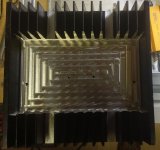
Milled Heat Sink have come
Hi everyone.. now waiting time is soon over.
This afternoon I could pick up the milled heat sinks, where I now can place 2 200Watts Resistors per side,, The milling has cost 300CHF equals about 330 USD.. Quite expensive just to make these Squares.. but it's not everyday..
Holding holes for the Sinks already drilled, only the holes for the Resistors have to be drilled. then everything's comes out of the Box and the Box will be Acid Cleaned and Anodized one more time as the heat sinks also.
As I have almost finished all other parts Stands and PCB, wiring tree so as soon the box comes back form anodizing, it will take max 2 days and then the amp is finished..
Thanks for watching..
Regards Chris
Attachments
Last edited:
Almost finished. will post more when really finish
Hi together
I'm sure everyone thought this amp never gets finished,,
You see, I do not have only a AMP to build with tons of hickups, and delays but also lots of personal time consuming Work.
In the meantime got a year older as well and really found not the time to finish that amp in one time..
So today Sunday 11th. I give myself kick in my butt, and now after 7 hours work amp looks like its gonna be finished this week
I'm waiting for some thermister and Varistors to arrive from Holland, which actually should be delivered by last friday, but this didn't happend.
Anyway all is in the box already 90 wires are done, and I think if I get these parts tomorrow so Wednesday of latest next Sunday this amp will have the top closed and found its position with he other amps..
shot a few Pics that you can see that it's almost finished,,I estimate another 4 hours and then should be good.. The amp has been tested for several months.. no problems what soever.
I wish to thank following people directly, because they gave me the inspiration to build that amp
Mr. Nelson Pass and Rod Elliot, and all members of DIY here, who gave me inputs or just read the whole thing..
Thanks
After the Amp is finished, I will reduce my time here by 90% because of daily life needs me more than ever,
Thanks every one here again, it was nice to meet all of you .. will be back sometimes, but I really have no Idea when..
with Respect
Chris
Attachments
-
 10. Tree way Connection RE.jpg115.5 KB · Views: 137
 -
 9. Amp Right Side.jpg575.4 KB · Views: 127
 -
 8. Amp Left side.jpg132 KB · Views: 137
 -
 7.Left Side PSU.jpg196.8 KB · Views: 152
 -
 6 From Front to back.jpg175.2 KB · Views: 147
 -
 5. Full Side Class A.jpg187.2 KB · Views: 258
 -
 4. side Class A.jpg255.8 KB · Views: 224
 -
 3. inside Top.jpg203.1 KB · Views: 245
 -
 2. Back Class A.jpg187.6 KB · Views: 261
 -
 1. Power on.jpg99.1 KB · Views: 247
The NEXT Step
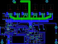
View attachment 883585Guys the Amp you see in the Pictures above, has as Ouptut Transisors 2 MJL4281AP
In the time when I was waiting for parts and also, in my spare time I designed a BOARD Dual Layers with 6 Output Transistors which will exactly fit the HEAT SINKS and everythings what comes with it, and this just to be able to connect 2 Ohm speakers,
and also RE is only 5Ohms instead of 7.5 which is the aboslute maximum for the 2 OUTPUT TRANSISTOR VERSION..
Regards Chris
Attachments
Just take your time and have fun designing/plannifying/realizing this build 
Looking forward to seeing the finished 'product' and your review of its sound 😉
Looking forward to seeing the finished 'product' and your review of its sound 😉
The Sound
Both of these build in Amps you seen in the picture has been tested in real environment and there is nothing to be not satisfied,
Sound is open Wide Heavy sweet and power fullwhere is should be..
My last frequencey measurements were 10 Hz - 200Khz linear with .2 Db in highs. and - 3 DB at 300khz
I have neough equippment at home ot test these Amp. Also I think 12 or more pairs of Quality loudspeakers, 4 turntables and so on..
The only thing what I do not like I still have some very Little Noise from PSU,, and therefore I designed the new PCB with 6 Output Transistor where I use a efficient filter on the Board.. we will see..
Havent heard the amp, with the big Transformers, and I think thats was the problem for the Nois 50hz and 200Hz.. because those run overload the full time..
Both of the amps have a running time or about 1000 Hours by now..
Before I build them into the case I renewd Heatsink Compound, cleaned the PCB and checked all Trasnistors and today when I hopefully get that spare components I still need, then Iw ill make a read out with the Oscilosope and then we know,, I will place the data here, whatever it comes out..
Regards
Chris
Guys,
When the build is finish, I will place all the Layouts, Schematc Cirquits and also Gerberfiles here,
So, it can be build without to have to worry that when finished it wouldn't work. Except is the selected parts are changed.
I just see that the parts which were missing till yesterday evening, has been delivered to my postbox at home. But since I'm still at my office, it will take a short while, until I can check if the parts have really been delivered, once I get home.
Last night I also was working on the amp, just to get it finish in this week, have done some metal work, which had to be done also.
I hope to be alble to finish that Amp this week tonight I may will be able to start it up with the big Transformers.Never have done that, except for testing the PSU..
Wait and see
cheers
Chris
NTC Thermister
So finally the NTC Thermister had been delivered this afternoon and I have soldered it to the place where those are supposed to be in that box
First try - Home Main fuse Breaker = Cut off..
The I changed from two 8 Ampere 5 Ohm Thermister in Parallel to two 8Ampere 5 Ohm Thermister to serial, and there we go, applied power the amp and both sides just started up, it's dream..
Anyway I have some other work to do also, on that box, so tomorrow when I come back from work at office I will get that amp ready to bring it to it's limits,,
Using a function Generator, Oscilloscope dummy load, real speakers, and also distortions Program on the Laptop to check if the amp works as expected.. I think it will.
So actually Sunday that Amp will be finish, by then I hope I have the Documentation ready for all of you.. Circuit will be available as well,
Guys, thanks, that I could be a part of this community.
Sincere, Chris Hes, BERN - Capital City, Switzerland
Another Step in finishing that Amplifier,.
Guys,
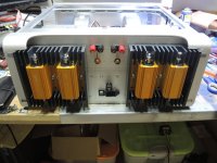
here a few pics of the state of that Class A - single End Amplifier,
Got myself in Building mood, and so made all the missing Cables, the one you see are inside the amp connecting the Rear Jacks and the PCB's.
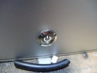
then, also got the Side panel (Present time only right side) fitted and Screwed on. Then also got Power Switch wired, and also Speaker Connection, as well as the input connectors.
Then connected input source my FOSTEX STUDIO MIXING CONSOLE, with that standing Turntable made in Austria Brand is Project..
sounds good and looks good..
Pushed the Power Button and there we are.. sound nice clean clear
Used Queen the Works Album to evaluate the flat sound of the songs,,like Radio GA GA..
I also have made a short Video, and it sounds fantastic, but there on my bench and in my working room is such a mess, I can't show that one,, hehehehe
Otherwise you guys might mean that I'm living in trash room..
Guess tomorrow the Amp will be finished, cooling hasn't been connected yet, this will happen tomorrow or Saturday Sunday whatever fits
As I thought, all Hum is gone, no noise anymore. I'm satisfied.
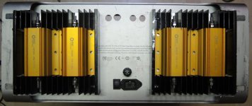
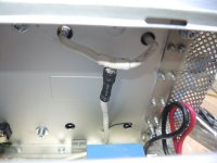
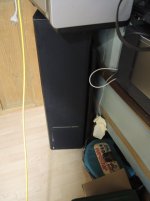
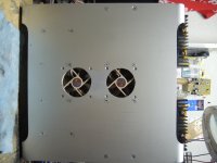
Picture 1 shows the underneath of the amp.. there also will be floating feet on the bottom, but if I put them on now, then those will loose the floating because getting scratched on the surface, which is made that the amp can be moved without to lifting up..
BTW Input Cable is Whirlwind, Microphone Stage Cable, Oxygen Free copper, double shielded with Copper and Carbon.. This cable has a very linear Sound and is very low noise.
Guys,
here a few pics of the state of that Class A - single End Amplifier,
Got myself in Building mood, and so made all the missing Cables, the one you see are inside the amp connecting the Rear Jacks and the PCB's.
then, also got the Side panel (Present time only right side) fitted and Screwed on. Then also got Power Switch wired, and also Speaker Connection, as well as the input connectors.
Then connected input source my FOSTEX STUDIO MIXING CONSOLE, with that standing Turntable made in Austria Brand is Project..
sounds good and looks good..
Pushed the Power Button and there we are.. sound nice clean clear
Used Queen the Works Album to evaluate the flat sound of the songs,,like Radio GA GA..
I also have made a short Video, and it sounds fantastic, but there on my bench and in my working room is such a mess, I can't show that one,, hehehehe
Otherwise you guys might mean that I'm living in trash room..
Guess tomorrow the Amp will be finished, cooling hasn't been connected yet, this will happen tomorrow or Saturday Sunday whatever fits
As I thought, all Hum is gone, no noise anymore. I'm satisfied.
Picture 1 shows the underneath of the amp.. there also will be floating feet on the bottom, but if I put them on now, then those will loose the floating because getting scratched on the surface, which is made that the amp can be moved without to lifting up..
BTW Input Cable is Whirlwind, Microphone Stage Cable, Oxygen Free copper, double shielded with Copper and Carbon.. This cable has a very linear Sound and is very low noise.
Attachments
-
 9. Polk Audio Test Loudspeakers.jpg203.7 KB · Views: 104
 -
 8. Closed Ventilation Channel.jpg195.4 KB · Views: 100
 -
 7. Side of the AMP the finish one..jpg258.4 KB · Views: 105
 -
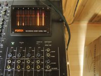 6. Mixing console Fostex.jpg172.9 KB · Views: 103
 -
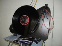 5. The sound Source.jpg185.3 KB · Views: 99
 -
 4. Amp power on.jpg124.2 KB · Views: 94
 -
 3. Ready to test.jpg252.8 KB · Views: 101
 -
 2. Amp Bottom underneath.jpg134.5 KB · Views: 91
 -
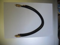 1.Input Cable.jpg83.9 KB · Views: 107
Last edited:
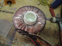
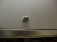
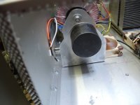
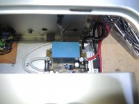
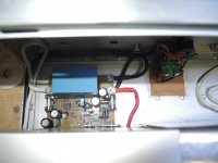
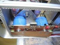
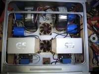
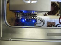
Nice looking build. From your pictures, though, it looks like your toroid transformers have a shorted turn with the mounting bolt that connects on both sides to the bottom plate. I can't see all the details so maybe I'm wrong. My apologies if that's the case.
Don't worry and no need to apologize
The Toroids are mounted on two Rubber Blocks, not connecting to each other.. both Bolts are in rubber molded, and do not have contact within the center of the toroid,. both are Floating..
Check out the picture,,
Is not finish yet but most is done, need to set the panel for left side, then Ventilation control and also the switchable 18 - 28 Watt Relays and Switches are not set yet.. but this ain't a problem parts are already build and all I need to do is to place them in the box..
Attachments

Last edited:
- Home
- Design & Build
- Construction Tips
- Building a Class Amplifier from Scratch