ClaudeG and Rob43 : has one of you tried to bypass the volume control , to use Aiyima a04 as a power-amp ? .
It would be very nice to see and read about how to do this.
Regarding the power supply - I have recently bought a mean well 24 V, 5A supply thats been recommended by Nelson Pass . It made a real, small improvement in my active system to drive my tweeters.
Here is the power supply:
Meanwell 24V 5A power supply and power cord – diyAudio Store
Test results here:
https://cdn.shopify.com/s/files/1/1006/5046/files/GST120A24-rpt.pdf
I have also tried different voltages yesterday. It seems that the sound gets a bit better when you increase the voltage from 19 v to 24 v. Even if you just drive a tweeter. Before I had a medical grade 24 v supply also from mean well but it does not sound as good as the new supply.
The mean well supply recommended by Nelson Pass sounds best without the Capacitance multiplier.
It would be interesting to see some measurements about the difference when driving the Aiyima with different voltages.
Whats your opinion about optimal voltage ? Is maybe 30 V the optimal to have the best sound with this amplifier, or is the quality of the supply more important ?
Last edited:
Of course, that's the first thing we started to do, see my previous posts here and on the othe thread...
We have currently an offboard motorised Blue Alps (not the best, but convenient) piloting both power amps directly. However, due to the lockdown we weren't able to remove the existing pots that are now useless in a fixed position and probably robbing a lot of music (mod to be evaluated).
Gilles tried a quick and dirty method: as I can't work on the unit due to the lockdown, he tried simply shorting the volume pot, linking directly the board legs side to side, shunting that way the awfull pot. IT DID NOT WORK, it can't be just shorted, it is still active somehow.
To progress on this I really need to get access physicaly to that unit again. I had last Wed for 30' and we were getting started with the second batch of mods, starting with removing the pot and we had a week off ahead. And then the President spoke on TV and decided to lock us down with immediate effect! Gilles had no other option than living at once our home to get back to his (250km away), with the amps. Shortest mod session ever...
Since then he carries the mods remotely with me, and the bigger mods requiring me will sadly have to wait for weeks. The pot is part of it: he can't remove the small board with his equipment, so is stuck for the moment.
Claude
Really. I use Elna Silmic II.It's a total of four pieces that definitely have som impact on the sound.
Hi Radelius,
You may want to read our posts.
There are actions ongoing around the DC coupling caps. There are 4 located between the OP amps and the chip amp, and 4 others between Op amps.
However, you may want to wait, as things aren't as straight forward as they seem regarding these.
More to follow when I will have the time
Claude
I guess it is OK to post failures, as this can save others from doing mistakes or enlighten us if you know better and have a solution.
It is not easy to work on a unit without its schematic and not even owning one. All numerous measurements are done by Gilles (who is foing a splendid job) in hope to understand / retroengineer the schematics. To go safe and because he hasn’t got the right equipment and only got started, these measurements are done unit off and with a cheap multimeter. That has of course limits… But there is no way to do better as we are locked down 250km from another and I have no physical access to the units. I am very lucky though, as Gilles considers this as a learning game, so if we blow a unit it is not a disaster and just 40$ that are gone. Not that we want to, but lucky us it won’t change our life. It will just hurt my ego designing the wrong process…
So following our modification map, here comes a strange mod : adding 1 cap (per channel) in the signal path !
Why doing it ?
Because it will hopefully enable us to remove 2 very average electolytic caps per channel in the signal path and that « no cap » is still the best cap ! Oh, forgot to say, the one we do add is a high quality PPP cap, we hope an addition you can’t hear or so.
And as we are in bi-amping configuration, we do basicaly hope to trade of 8 awful caps for 2 great PPP caps… costing us 3$ in total.
We will come to the caps we remove and the benefits of this mod in another post. For now, for the record :
1- If you don’t have any issue with DC coming from your source, you don’t need doing this mod (you are already covered). Note you may have already DC blocking caps at the output of your source or a device that is DC coupled. But in case of a failure you won’t have the (extra) protection of this mod
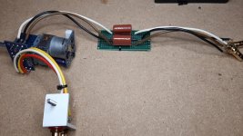
2- Yes, we fit these caps outside the units, because we wanted them before the potentiometer (and not after as in the unit) piloting gour 2 amps. But these are amongst the smallest high quality PPP caps and I see no reason why you shouldn’t be able to fit them inside the unit. We didn’t, but as hint I see 2 possible locations. One is fiddling with the back of the RCA plug in the unit to insert them in the signal path (plenty space there), the other one could be removing the potentiometer board to insert a better pot and while at it connect these caps.
Now to the caps. I have a pair lying here but had no time to test them. These Panasonic ECW cost both less than 3$ and have been highly recommended by « Fab » here on DIYaudio, in posts and also in the BOM of his excellent amps (USSA and many others). I see no reason to doubt him. They are way smaller and cheaper than my Cornell Dubilier 940C, a cap that is so excellent and neutral I see no reason to go beyond for my needs.
The positive is that for Gilles, the addition of Panasonics has been absolutely transparent as he couldn’t here it. That is they are either excellent aswell… or very good and our low budget amp / ears don’t make the difference at that level so they are more than good for the job. Anyway, they probably stay and don’t harm.
Now to the value. If you aren’t familiar with high pass filters and low cut frequencies, I encourage you to browse. The minimum cap value here seems mainly to depend on the pot impedance and what cut off frequency (Fc) you want, bearing in mind you do still cut somewhat at higher frequencies than Fc. Oh, and I doubt many owners use this budget amp with real full range LS that do really go down to 20Hz.
Anyway, we went for 4 .7uF because this value « higher than needed » came at the same price and in similar size. If you go for a 50k pot as we did, you could probably get away with a 0,6uF cap (minimum value) or slightly higher. The small green pot we have in our units seems to be 25k or so, so you may want 1.5uF caps or so. Dead cheap and small if you go for the PPP Panasonics listed here, excellent advice from Fab !
We didn’t lose anything in terms of music, or couldn’t tell with this set up and our ears, but we still hope we did that for a good : the real gain might come from the bottlenecks we hope to remove.
Bottom line is these caps are excellent VFM and can stay or go. They are a success. However, what follows is less so, stay tuned… and don’t jump on this mod.
Enjoy music
Claude
It is not easy to work on a unit without its schematic and not even owning one. All numerous measurements are done by Gilles (who is foing a splendid job) in hope to understand / retroengineer the schematics. To go safe and because he hasn’t got the right equipment and only got started, these measurements are done unit off and with a cheap multimeter. That has of course limits… But there is no way to do better as we are locked down 250km from another and I have no physical access to the units. I am very lucky though, as Gilles considers this as a learning game, so if we blow a unit it is not a disaster and just 40$ that are gone. Not that we want to, but lucky us it won’t change our life. It will just hurt my ego designing the wrong process…
So following our modification map, here comes a strange mod : adding 1 cap (per channel) in the signal path !
Why doing it ?
Because it will hopefully enable us to remove 2 very average electolytic caps per channel in the signal path and that « no cap » is still the best cap ! Oh, forgot to say, the one we do add is a high quality PPP cap, we hope an addition you can’t hear or so.
And as we are in bi-amping configuration, we do basicaly hope to trade of 8 awful caps for 2 great PPP caps… costing us 3$ in total.
We will come to the caps we remove and the benefits of this mod in another post. For now, for the record :
1- If you don’t have any issue with DC coming from your source, you don’t need doing this mod (you are already covered). Note you may have already DC blocking caps at the output of your source or a device that is DC coupled. But in case of a failure you won’t have the (extra) protection of this mod
2- Yes, we fit these caps outside the units, because we wanted them before the potentiometer (and not after as in the unit) piloting gour 2 amps. But these are amongst the smallest high quality PPP caps and I see no reason why you shouldn’t be able to fit them inside the unit. We didn’t, but as hint I see 2 possible locations. One is fiddling with the back of the RCA plug in the unit to insert them in the signal path (plenty space there), the other one could be removing the potentiometer board to insert a better pot and while at it connect these caps.
Now to the caps. I have a pair lying here but had no time to test them. These Panasonic ECW cost both less than 3$ and have been highly recommended by « Fab » here on DIYaudio, in posts and also in the BOM of his excellent amps (USSA and many others). I see no reason to doubt him. They are way smaller and cheaper than my Cornell Dubilier 940C, a cap that is so excellent and neutral I see no reason to go beyond for my needs.
The positive is that for Gilles, the addition of Panasonics has been absolutely transparent as he couldn’t here it. That is they are either excellent aswell… or very good and our low budget amp / ears don’t make the difference at that level so they are more than good for the job. Anyway, they probably stay and don’t harm.
Now to the value. If you aren’t familiar with high pass filters and low cut frequencies, I encourage you to browse. The minimum cap value here seems mainly to depend on the pot impedance and what cut off frequency (Fc) you want, bearing in mind you do still cut somewhat at higher frequencies than Fc. Oh, and I doubt many owners use this budget amp with real full range LS that do really go down to 20Hz.
Anyway, we went for 4 .7uF because this value « higher than needed » came at the same price and in similar size. If you go for a 50k pot as we did, you could probably get away with a 0,6uF cap (minimum value) or slightly higher. The small green pot we have in our units seems to be 25k or so, so you may want 1.5uF caps or so. Dead cheap and small if you go for the PPP Panasonics listed here, excellent advice from Fab !
We didn’t lose anything in terms of music, or couldn’t tell with this set up and our ears, but we still hope we did that for a good : the real gain might come from the bottlenecks we hope to remove.
Bottom line is these caps are excellent VFM and can stay or go. They are a success. However, what follows is less so, stay tuned… and don’t jump on this mod.
Enjoy music
Claude
Attachments
So we did quite a few measures and our understanding for now is as follows :
0- The layout is such that each op amp is dealing with one channel and that caps under or above it are related to that channel. No mixing here, so there is only one confusion with one cap in the row of 5. More later. This is not a simple stage to symmetrise the signal. In fact it is used also as a slight gain stage, the first stage being with gain x2. The last stage is gain = 1. I am less familar with symmetric signals as I have none in my own HIFI. As it turned out with our failure (post to follow), there might be more to it, help welcome. That stage we also assumed the volume pot was purely acting as an attenuator outside of everything else, read not included into any gain stage etc. That needs now more digging.
1- The 4 electrolytic caps between op amps and chip amp are very probably DC blocking output caps from the last OP amp stage and as we it is a differential output there are 2 for each channel. We still intend to replace them with better ones. Given the impedance of the next stage we hope as posted Wima MKS with only 1uF should do the trick, but there only one way to find out .
2- The 5 electolytic caps between the pot and the op amps. The one in the middle seems to be for VMID, an artificial way to have something that shifts voltage to enable you teh equivalent of a PS with -6V (or so) and +6V while you only have a +12V power supply and ground (0V). There is a voltage splitter and playing with +In of op amps allows shifting voltages to get in relative terms what you want. In short, that cap is not really the usual PS cap for op amp, something Rob is already playing with his bypasses and something we will play with aswell. This is for VMID but is « reference PS related ». We will address this.
3- The other caps seem to be DC blocking caps. One at the entry of op amp stage 1, one for whatever reason between stage 1 and stage 2, also DC blocking I am assuming. It is odd. However, these caps have their function and there is more to it as we got it… wrong !
Let’s see what happened…
Claude… and Gilles
I used WIMA 4,7uf caps, cuts low frequenciesGiven the impedance of the next stage we hope as posted Wima MKS with only 1uF should do the trick, but there only one way to find out .
Hi Dr Mordor
That's an interesting point. The spec sheet says the input impedance of the TI Chip amp is 24k... so 1uF caps should be good for 5Hz Fc.
Are you saying that with that chip, putting at its 4 inputs DC blocking caps of 4.7uF did stop bass frequency, hence needing more capacity?
Just to make sure I got you right and in hope to save a stupid mod then, although I would like to understand how that can be (spec sheets are usualy accurate)
Thanks as ever!
Claude
I know about this. you can hear itThat's an interesting point. The spec sheet says the input impedance of the TI Chip amp is 24k... so 1uF caps should be good for 5Hz Fc.
Thanks for the feedback Dr. Mordor...
Well, I already purchased the caps, so might think of some back up plan to still improve on the OEM ones should that indeed fail to work - you have tried, I didn't, relied solely on spec sheet.
Worst case I know where to try those I bought, should they not give the expected result. For now I have sadly a bigger question mark on hand with this unit... perhaps you can cure that one
Thanks against, good Dr ;-)
Claude
Last edited:
Let’s tackle the above mentioned cap in the middle of the 5. This is part of our « K » mod, except that cap is not exactly the PS cap we thought, so we still need to tackle conventional +V and ground elsewhere, that one is for VMID.
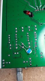
TBH, I didn’t expect any change at all as tackling this one is tricky. Of course you could enhence VMID at OP amp level individualy with bypass caps, but I felt this could be worth as upsetting +In of the op amp with time shifted references. I therefore decided to keep the current layout, having only one VMID reference for all stages. Now that comes from the 10uF. To make that cap (and voltage) stable and « fast reacting if needed » it is good to have it bypassed with say 0.1uF. I assumed this was already the case, at SMD level. But who knows without the schematic ?
We had no expectations and we did it initialy quick and dirty, just to confirm it was a wasted cap mod. However, we di dit nicely, with an excellent Murata C0G 0.1uF bypass cap.
And it worked slightly to our suprise. But differences are so small, with no downside though. Findings were :
- No downside at all
- Bass on some music (not all) gained in definition and substance (+1)
- Treble is more defined, clearer but without getting to analytic (+1)
- Mids are unchanged
At the end Gilles gave it +1. Indeed a minor step, but still a step and cost 0.5$ soi s no brainer – stays !
It is on the verge of noticing such a mod, lucky we have 2 amps to compare directly in a matter of seconds. However, given the magnitude of change, we decided to group some other mods (supposed secondary PS caps bypass) as it would cost more time to try them out individualy given their low price and expected low results. Should it reveal downsides or mitigated results or great outcomes, that we would split these again.
To be followed with the 4 other, completely different as DC coupling caps… that is as we understood it.
Claude… and Gilles
PS : the legs and installation on the pix where just to give it a try as we didn’t expect it to work so wanted to use the cap elsewhere and be able to refit it. It turned out it worked better than expected and on the next pix you will see the definitve installation.
Attachments
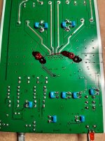
Let’s tackle mod « E ». That’s a bit trickier, but seemed still easy. The reason we installed the Panasonic ECW blowking caps was we wanted to get rid / shunt the awful DC blocking electrolytic caps at the op amp entry and between stages. Read C4, C11, C16, C19. « No cap » being cheap and « best cap », this looked like a nice must do.
We had installed our Panasonic DC blocking caps at signal entry, had still the (4) DC coupling caps between Op amps and Chip amp, so what could possibly go wrong ?
Inbetween it is a bit of an unknown yet. We took around 100 measurements, sadly just static and with no current, to try to understand how the unit works there, how the caps are connected and avoid disaster. Our understanding has been posted a few posts earlier.
In short, considering only the signal path, we assumed something like the following order :
- RCA entry plugs
- pot to attenuate the signal
- 1st DC blocking cap
- Stage 1 of op amp with slight gain of 2 and 2nd DC cap at its output (I wonder why ???)
- Stage 2 for symmetrical signal, gain 1 of course
- 3rd DC blocking cap between Stage 2 output and Power Chip input, out of our current scope, these are the 4 top electrolytics we will address at a later point.
It all looked so easy. Get a DC blocking caps at entry before our Alps pot (our Panasonic caps), go to device RCA plugs, go through device input (sadly still through another pot, the OEM one as not removed yet), no need for the 1st DC blocking cap (= shunt) as we already got one upstream with the Panasonic, defo no need for the 2nd between stages DC blocking cap as the OPA1656 have little output offset and gain is unitary… plus we have anyway at the very final Op amp stage output anyway DC blocking caps before the chip amp.
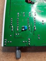
So we shunted quite confidently, but not completely, the 4 caps. Lucky us, we didn’t take them out and just jumped them with a wire. And then.. no sound anymore. Failure. Big sweat. We undid 2 shunts, assuming at least the shunts between stages had no reason to be there, whereas the ones at the input weren’t maybe really straight at entry as we thought. Failure, no sound. Bigger sweat. At that stage we decided to stop experiments quickly, didn’t indeed even tried keeping the interstage caps as normal and bypassing only the entry ones (only combo left), as we understood… we understood nothing ! there is Dc at play where we don’t expect it, possibly an active stage or a bias somewhere we missed.
The attached pix illustrate what we did and we don’t understand as of now why it didn’t work. Indeed, without unit on hand I struggle and waste time, so any help is welcome. Good Dr. Mordor & Co, maybe ?
Perhaps the unit is not working as I thought… and the volume control is not that passive ! It could perhaps be active with other parts we didn’t spot… or, who knows, maybe acting on the op amp stages à la Baxandall sound corrections but playing with the feedback loop to adjust gain ? Or whatever...
It has been a long day so we stopped that part there.We either need to understand how that input section works before experimenting and assuming blindly… or go for milder mods as keeping the existing DC blocking caps and bypassing them with better smaller ones or replacing them altogether with better ones (but space is very tight and value to chose unknown as no clue what impedances we are dealing with).
Last but not least, as posted, Gilles tried to shunt the volume pot, connecting input and output as quick measure before I could access the unit and remove the board properly. It didn’t work (!!!), eventhough shunted the volume pot is still active (!!!) and so there is more at play here !
Of course there must still be a way to replace the pot alone with a fixed quality resistor network if needed, or even the entire board if there is no hidden device under it, but at the end we need to understand what these op amps really do and how the volume adjustment works.
Ideas welcome, meanwhile moving to the next mod while brainstorming. Oh, forgot to say,… Good unit : we removed all shunts and, hourra, all is working again J
Claude… and Gilles (the former puzzled, the latter amused !)
We had installed our Panasonic DC blocking caps at signal entry, had still the (4) DC coupling caps between Op amps and Chip amp, so what could possibly go wrong ?
Inbetween it is a bit of an unknown yet. We took around 100 measurements, sadly just static and with no current, to try to understand how the unit works there, how the caps are connected and avoid disaster. Our understanding has been posted a few posts earlier.
In short, considering only the signal path, we assumed something like the following order :
- RCA entry plugs
- pot to attenuate the signal
- 1st DC blocking cap
- Stage 1 of op amp with slight gain of 2 and 2nd DC cap at its output (I wonder why ???)
- Stage 2 for symmetrical signal, gain 1 of course
- 3rd DC blocking cap between Stage 2 output and Power Chip input, out of our current scope, these are the 4 top electrolytics we will address at a later point.
It all looked so easy. Get a DC blocking caps at entry before our Alps pot (our Panasonic caps), go to device RCA plugs, go through device input (sadly still through another pot, the OEM one as not removed yet), no need for the 1st DC blocking cap (= shunt) as we already got one upstream with the Panasonic, defo no need for the 2nd between stages DC blocking cap as the OPA1656 have little output offset and gain is unitary… plus we have anyway at the very final Op amp stage output anyway DC blocking caps before the chip amp.
So we shunted quite confidently, but not completely, the 4 caps. Lucky us, we didn’t take them out and just jumped them with a wire. And then.. no sound anymore. Failure. Big sweat. We undid 2 shunts, assuming at least the shunts between stages had no reason to be there, whereas the ones at the input weren’t maybe really straight at entry as we thought. Failure, no sound. Bigger sweat. At that stage we decided to stop experiments quickly, didn’t indeed even tried keeping the interstage caps as normal and bypassing only the entry ones (only combo left), as we understood… we understood nothing ! there is Dc at play where we don’t expect it, possibly an active stage or a bias somewhere we missed.
The attached pix illustrate what we did and we don’t understand as of now why it didn’t work. Indeed, without unit on hand I struggle and waste time, so any help is welcome. Good Dr. Mordor & Co, maybe ?
Perhaps the unit is not working as I thought… and the volume control is not that passive ! It could perhaps be active with other parts we didn’t spot… or, who knows, maybe acting on the op amp stages à la Baxandall sound corrections but playing with the feedback loop to adjust gain ? Or whatever...
It has been a long day so we stopped that part there.We either need to understand how that input section works before experimenting and assuming blindly… or go for milder mods as keeping the existing DC blocking caps and bypassing them with better smaller ones or replacing them altogether with better ones (but space is very tight and value to chose unknown as no clue what impedances we are dealing with).
Last but not least, as posted, Gilles tried to shunt the volume pot, connecting input and output as quick measure before I could access the unit and remove the board properly. It didn’t work (!!!), eventhough shunted the volume pot is still active (!!!) and so there is more at play here !
Of course there must still be a way to replace the pot alone with a fixed quality resistor network if needed, or even the entire board if there is no hidden device under it, but at the end we need to understand what these op amps really do and how the volume adjustment works.
Ideas welcome, meanwhile moving to the next mod while brainstorming. Oh, forgot to say,… Good unit : we removed all shunts and, hourra, all is working again J
Claude… and Gilles (the former puzzled, the latter amused !)
Attachments
Let’s tackle the rest of mod «G ». We already bypassed a some PS caps with some success, but there are more on the list. We will tackle most of them except the bits we could do directly around the op amp PS.
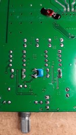
That means bypassing various smaller PS electrolytic caps, 6 in totaln with either Murata 0.1uF (C0G, had to go for 0.082uF in fact due to the 0.1uF being in back order) or 2.2uF Murata X7R quality caps. All these 6 caps we intend to treat are quite close to the front facade, the bigger 470uF caps have been bypassed with 2.2uF, the remaining ones (100, 120 and 22 uF) with 0.1uF caps.
So that’s were we decided to be more time efficient with our tests. Let’s face it, we spend a lot of time with some unknown sections of this amp. Some tweaks have been great, other hasardous. The problem is we do’nt have the schematic so we can only guesstimate what the caps we see are there for.
I have no certainty on what these caps stand for. If I would have been the manufacturer I would have splitted the 12V PS to address more or less separately :
- Op amp PS, critical, and to be sure we will address it also elsewhere
- Low voltage Chip amp analogue PS, as affecting possibly the important first amp stages in the TI chip (?), critical
- Low voltage Chip amp digital PS, possibly not too critical
There are 6 unknown caps, I would have used 3 of them, the biggest here with the right voltage, to address these points. So I could possibly just tweak / add a bypass these 3 big caps and get away with it. Or not. The other caps could be secondary, but we don’t know. I am nearly sure that the 6.3V cap is only for 5V or 3.3V, so « commands » and not at all sound related, so that one possibly doesn’t need anything !
However, I am quite confident adding clever bypass caps can’t deteriorate sound (and if so, we can then look into the details). The bypass caps here cost less than half a $, and as we aren’t sure anyway and may miss something, why not treating them ALL as a batch ?
Bypassing it all in one go, job done, and evaluating the results if any. No big hopes, so bulk treatment, overkill of course, but at least we know if wasting more time is needed on these caps or not.
And that’s how the bulk treatment was perceived :
- Better mids, especialy voices, +1
- Treble a bit more airy, +1
- Better soundstage, +1
- Fun factor, +1
No downside and overall a very small step for little money, +1.
Not related to this mod, but at this stage we feel the bass has overall less benefited from all past mods together (whereas treble and mids are addictive), so we keep an eye on it. At the end, when most mods are done, we may have to adjust that or make choices. Just a not at this stage.
Claude… and Gilles
Attachments
")
Hmm.... The tpa 3251 chip has four inputs , and with BTL coupling ( as in Aiyima ) the inputs in the chip are bridged, meaning the single end input from RCA has to be converted to balanced for BTL function. Thats maybe one of the function the OP:s have ? At least thats what Im thinking. But I can be wrong on this.
Thanks anyway that you tried to modify the input caps.
Thanks anyway that you tried to modify the input caps.
Last edited:
Hi Audientid14,
Yes, of course, as posted already. Making a symmetrical (balanced) signal while also having a gain of 2. Thanks for your kind post, if any other idea don't hesitate
Hi Chips666,
Always a good idea, in fact I use already the schematic from the 3251 eval board, looks closer to this unit... but nothing on the forefront, not even in the one you posted. But also thanks for trying
It is what Aiyma did with the volume adjustment that is intriguing and perhaps not as conventional as it seems... or if not then something around of that signal path
Digging
Claude
- Home
- Amplifiers
- Class D
- Aiyima TPA3251 Modification Build Thread!