Hi Audientid14,
You may want to wait until we are done with bypass caps, some bits are still under evaluation and we had to order again... you don't want to do that ;-)
Oh, and Rob is on bypass caps aswell, in a different way... worth waiting IMHO.
Anyway, regarding your questions
How long is the distance between the legs of the bypass caps ?
=> Not sure I understand that, but our blue bypass caps have legs spaced by 2.5mm and so do the existing small electrolytic caps we bypass on the unit.
The two big power caps - is it 1 cm ?
=> 7.5mm
But why don't measuring all this on your own unit?
I hope this helps
Claude
It feels that putting the board in a bigger box could be the way to go. The current chassis is limiting the size of caps and the volume control.
Great thread though, loving it.
Great thread though, loving it.
Well, Lilolee, we kept the casing(s) as it is convenient and not that limiting for what we want to keep inside it/them, but worst case the lid(s) could come off I guess, depending on how far one wants to go. Until now that's fine and I tried to stick to that - Gilles is less concerned with that potential limitation.
As you know Gilles was crazy enough to pack 2 of these units into an old 70's amp, so we enjoy a lot of space for these amps, plus 2 SMPS filters, plus a large size Meanwell SMPS, plus a motorised Blue Alps volume control (with its own PS and also remote control board), plus an input board with large PPP DC blocking caps in case of... and one day source selection board as we want more than one input.
Is that all? Nah, we should be able to fit a small buffer after the pot "à la B1", so we can peacefully add Pass latest 6-24 active Xover... to really take full benefit of the bi-amping 🙂
Then it shall be full packed in a satisfying manner... unless a small DIY DAC... nah, that should have really its own casing 🙂)
You know it all, mate
Full credits to the owner, Gilles, fiddling with all this and also having planned a lot of connectors to be able to switch from 1 amps to the other and also to 2 amps within secs, as well as taking every bit out and in fast to enable our numerous mods...
Claude
Last edited:
You know it all, mate
Haha, I wish I did. There are days when I feel I know nothing

Anyone tried this one
TPA3251 Class D Digital Stereo HiFi Audio Power Amplifier Board 175W+175W| | - AliExpress
Breeze audio
TPA3251 Class D Digital Stereo HiFi Audio Power Amplifier Board 175W+175W| | - AliExpress
Breeze audio
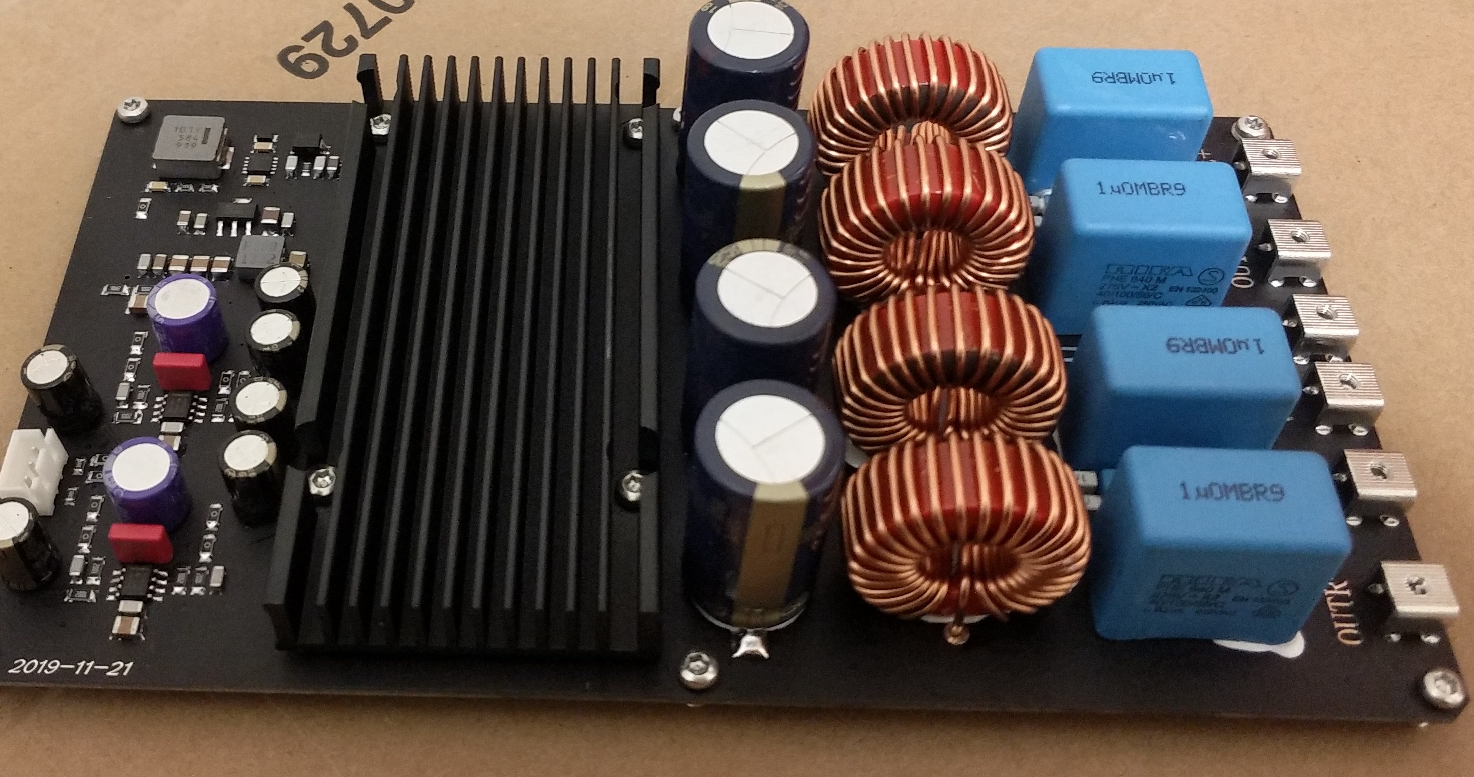
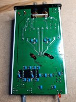
Going for the last part of mod « E », that is bypassing the remaining electrolytic DC blocking caps with the usual 0.1uF C0G Muratas. The DC blocking caps we need to keep (and hence to bypass) are the ones between stage 1 and 2 of the op amps and the ones at the output of the op amp section / input of the chip amp (close to the dissipator).
That means bypasing 2 caps in the signal path per channel. The findings are :
- no downside at all
- soundstage and location of instruments are a tad better
- A bit more airy
Mod gains are somewhere between +0,5 and +1, probably close to +1 on most bits.
What does that mean ? It means that it is a very small gain, nearly marginal, admittely for little money. This is no surprise : taking 1 electrolytic cap completely out of the signal path brought us +1. That is the maximum gain (volontary cap coloration aside to spice sound) as no cap is best cap. So it is of no surprise that tweaking around an existing electrolytic cap, bypassing it, or even replacing it with MKS or PPP caps, will give at best +1, at worst 0 gain. Here we merely played it easy and low cost, bypassing only the existing caps, and we get an end result very close to +1… bypassing 2 caps in the signal path. Quite consistent.
Means also that all that we still plan to do around this bit (replacement with Elna Caps, with Wima caps, all bypassed or not) will presumably yeld very very little further gain… if at all. So let’s be reasonable with parts and budget. BUT it might help us at the end adjusting the sound to our taste, that’s why we spent a few extra $ for these. Oh, and for science, so YOU know…
There is also another conclusion : this unit doesn’t respond a lot to DC blocking cap tuning. On the other hand, all the other high quality units I know, starting with my recently built Pass preamp, do respond A LOT to DC coupling cap tuning. Let’s face it, this is a nice and consistant unit, very balanced now and very seducing overall… but still built around a Chip amp and definitely not the last word in terms of resolution and transparency on complexe orchestration, not to mention room information / soundstage depth.
Point IMHO : tweaks have to be reasonable around this unit, there are a lot of things to do to bring this unit from an « OK level » to an indeed enjoyable « great level », but you won’t turn a GTI into a formula 1 car. Let this amp seduce us with all what we hear from it, while best not trying to find out what we are still missing in reality.
Next tweak will be around op amp’s PS, let’s hear if we find something there…
Claude… and Gilles
Attachments


Going for the last part of mod « G »… and perhaps the last main tweak we will post for a while, as the « main bits I need to do myself on the unit » will have to wait for the end of the lockdown. Well, there are still some minor tweaks as « caps flavour » or « resoldering the terminals », but that’s really it… unless someone comes up with a brillant new idea to try out ?
But for the moment let’s bypass the op amp’s PS directly at the op amps legs, where it matters most. I have to say that what we are doing here is a quick and dirty, easy and cheap mod - in no comparison to what Rob is carrying out around the same topic, with far more care, methodology and investment ! If you want to know all about that tweak, I suggest you wait for his posts as he got already started on an ambitious and fascinating testing process. Credits to him for that idea !
Here, we went the very easy way, adding caps under the board. Non expensive ones, connecting bypassing caps at the +V and –V legs of each amp in 2 steps :
- 0.1uF C0G Murata bypasses
- 10uF X7R Murata bypasses
These should « just » still fit under the board, despite the numerous caps now in that area. We are still on it…
If all goes as planned, we will assess the gain with the 0.1uF bypass alone, and then with both bypasses together (they fit different purposes), and once done we will post the results here as usual.
Enjoy music
Claude… and Gilles
Hi amigos,
New TPA3251 that looks a good candidate for DIY project :
4X Samsung FC main caps 1800 uf / 50V

Another one as well :

New TPA3251 that looks a good candidate for DIY project :
4X Samsung FC main caps 1800 uf / 50V
Another one as well :
Last edited:
Going for the last part of mod « E », that is bypassing the remaining electrolytic DC blocking caps with the usual 0.1uF C0G Muratas. The DC blocking caps we need to keep (and hence to bypass) are the ones between stage 1 and 2 of the op amps and the ones at the output of the op amp section / input of the chip amp (close to the dissipator).
That means bypasing 2 caps in the signal path per channel. The findings are :
- no downside at all
- soundstage and location of instruments are a tad better
- A bit more airy
Mod gains are somewhere between +0,5 and +1, probably close to +1 on most bits.
What does that mean ? It means that it is a very small gain, nearly marginal, admittely for little money. This is no surprise : taking 1 electrolytic cap completely out of the signal path brought us +1. That is the maximum gain (volontary cap coloration aside to spice sound) as no cap is best cap. So it is of no surprise that tweaking around an existing electrolytic cap, bypassing it, or even replacing it with MKS or PPP caps, will give at best +1, at worst 0 gain. Here we merely played it easy and low cost, bypassing only the existing caps, and we get an end result very close to +1… bypassing 2 caps in the signal path. Quite consistent.
Means also that all that we still plan to do around this bit (replacement with Elna Caps, with Wima caps, all bypassed or not) will presumably yeld very very little further gain… if at all. So let’s be reasonable with parts and budget. BUT it might help us at the end adjusting the sound to our taste, that’s why we spent a few extra $ for these. Oh, and for science, so YOU know…
There is also another conclusion : this unit doesn’t respond a lot to DC blocking cap tuning. On the other hand, all the other high quality units I know, starting with my recently built Pass preamp, do respond A LOT to DC coupling cap tuning. Let’s face it, this is a nice and consistant unit, very balanced now and very seducing overall… but still built around a Chip amp and definitely not the last word in terms of resolution and transparency on complexe orchestration, not to mention room information / soundstage depth.
Point IMHO : tweaks have to be reasonable around this unit, there are a lot of things to do to bring this unit from an « OK level » to an indeed enjoyable « great level », but you won’t turn a GTI into a formula 1 car. Let this amp seduce us with all what we hear from it, while best not trying to find out what we are still missing in reality.
Next tweak will be around op amp’s PS, let’s hear if we find something there…
Claude… and Gilles
Just to be absolutely sure - is the bypass with a link ( red arrows ) the first capacitors after the volume control ? The one that could be done without any downside at all ?
Attachments
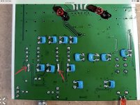
In red are the shunts!
That can only be done if you are dead sure there is no DC input... in our case we fitted PPP caps elsewhere offboard. Please refer to the appropriate post were all is detailled!
Claude
That can only be done if you are dead sure there is no DC input... in our case we fitted PPP caps elsewhere offboard. Please refer to the appropriate post were all is detailled!
Claude
Hi amigos,
New TPA3251 that looks a good candidate for DIY project :
4X Samsung FC main caps 1800 uf / 50V
Where can I see prices? Looks good.
In red are the shunts!
That can only be done if you are dead sure there is no DC input... in our case we fitted PPP caps elsewhere offboard. Please refer to the appropriate post were all is detailled!
Claude
I have an active dsp filter ( Dbx driverack pa2 ) to each Aiyima a04 with xlr-rca cables and Im pretty sure that the output from the filter is free from DC offset .
The balanced input suggestion was a tempting one to try out.
But Im not really sure how to do it.
See here -The balanced input suggestion was a tempting one to try out.
But Im not really sure how to do it.
https://www.diyaudio.com/forums/class-d/276982-tpa3251d2-145.html#post6186207
Careful! The op's are running on single supply, GND-12V. So the OP's must have a virtual ground at 6V. You can't connect the inputs to something that is not separated by a capacitor. That's how I understand it anyway.
Avoiding Op-Amp Instability Problems In Single-Supply Applications | Analog Devices
Have a nice week end/S
Avoiding Op-Amp Instability Problems In Single-Supply Applications | Analog Devices
Have a nice week end/S
Last edited:
Where can I see prices? Looks good.
TPA3251 carte amplificateur de puissance HIFI 175W ultra faible distorsion carte amplificateur de puissance numerique haut de gamme classe D amplificateur de puissance sanglier | AliExpress
and other version here :
Carte amplificateur de puissance numerique HIFI TPA3251 double canal 175W + 175W amplificateur Audio classe D | AliExpress
As already said, you really need to know what you are doing for this mod... and if you don't better stick indeed with a 0.1uF bypass of the input electrolytic. Not that it matters anyway a lot in terms of sonic gains, so go the easy and painless way
Just for memory, the signal input of the 1st stage here (-In) is not at +6V, the other (+In) is as it is a single supply. In any case, WE have no DC as WE do have a DC blocking cap elsewhere re first stage entry. However, you DO in any case need a DC blocking cap between stage 1 and 2. And we kept that one. You do need one at the final op amp stages output / input of TI chip.
But again, better know what you are doing and if not don't jump anything and just bypass the existing 'tic cap with small caps, job done... or fit other DC blocking caps of your flavour taking care of not creating a too bad high pass filter, so again you need to understand what you are doing.
Claude
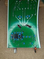
So… we added bypass caps at the +V and –V legs of each amp in 2 steps :
- 0.1uF C0G Murata bypasses
- 10uF X7R Murata bypasses
Just to explain our idea here… if all would be done perfectly in the unit, none of these bypasses should bring any sonic gain. The 10uF bypass is to make sure each op amp gets separately and as directly as possible enough « oomph » and reserve regardless what is pumped on the PS, while the 0.1uF is there for 2 reasons – making sure there are no OPA oscillations and also helping reducing the impedance of the PS at some frequencies, read more instant better feed. Both together should form a nice combo to filter the OPA PS and ensure a quick and nice current feed. We also hope the (relatively small) X7R cap enhences the existing big electrolytics response, why the diminutive C0G cap enhences all the PS caps as usual for bypass caps. Both caps need to be as close as possible to the OPA legs - if a choice is to be made then the 0.1uF is the most critical of the two. The most experienced here reading me in other sections will now that to be « closest to the legs » I usualy solder the additional parts directly on the OPA legs or on its small board… not that far away near unit « ground level ». But that’s more delicate to do, is less flexible while what we are doing here should still hopefully do the trick.
Of course Rob is going much farther in that PS bypass idea, using various high quality bypass caps in his tests. These are probably much better, but not as easy to fit nor as cheap, so consider our idea the poor man’s basic solution. That doesn’t mean you can’t get a lot of the benefits for very little hassle. In a perfect world though, you wait for Rob’s posts before ordering so you know where to go – we just had all this already in mind a couple of weeks ago when we ordered our (relatively qualitative) parts, but with insight we would now wait to find out what are the most appropriate parts to go for.
Note we went the trouble to do all this from underneath the board. You don’t have to is you have an OPA1656 : as said, just fit the caps above the DIP8 (under the top casing), much easier and possibly even better as shorter distance to OPA legs you want to bypass. Why didn’t we ? We like challenges J ! OK, we wanted to keep the top free for other tests to come where only bigger caps come into play, waiting also for Rob’s findings. Note also Gilles safe idea of fitting some black isolation tape to avoid any trouble with the holes connecting the board layers, just in case…
We assessed the gain initialy with the 0.1uF bypass alone, and then with both bypasses together. Our findings for the 0.1uF bypass are the following :
- it enhences all our initial findings and gains we obtained with the OPA1656 yweak
- it brings sunshine, like opening a window
- it sounds nicer, more present, has more flesh and depth and impact
- it sounds as if louder, possibly due to a lower noisefloor (per experience, no measures)
Overall a +2 gain, so at 1$ for both OPA this is possibly one of the best VFM mod we had and a keeper – our little amp is crying for it !
As of the 0.1uF + 10uF bypass, that is still under close evaluation as the precise results will guide us to future options from « take them out » to « put more of them, or different ones ». To make sure we go in the right direction the second amp will be fitted with the 0.1uF bypass only so we can compare directly (as usual) the effect of that single mod once all is ran in (just in case).
Enjoy music
Claude… and Gilles
PS: middle picture is with only 0.1uF bypass, others with 0.1uF and 10uF
Attachments
Last edited:
If the AIYIMA follows the TI EVM's configuration, then the virtual ground should be at pin 3, not pin 4. Pin 4 should be true power GND, but to be safe, it might be best to connect the XLR braid to AGND at a different point at the AIYIMA amp - the shield of the RCA input should be fine.The op's are running on single supply, GND-12V. So the OP's must have a virtual ground at 6V.
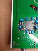
If I take the signal from the xlr configuration, balanced out from the dbx pa2, is it possible to get rid of the op amps and link the signal directly to the dip 8 adaptor ?
How do you do it , in which holes do you link the 3 signals from the L and R xlr cable ?
How do you do it , in which holes do you link the 3 signals from the L and R xlr cable ?
Attachments
- Home
- Amplifiers
- Class D
- Aiyima TPA3251 Modification Build Thread!