So... after all this unit seems to work nearly as anticipated, nothing fancy but a few bits...
1- The potentiometer is a classical one, a passive device at input. You can't just shunt it because if you draw a schematic you will find that you will always have a connection to ground (max level and connecting line in and out) regardless. Min level doesn't help, so eventhough you connect In and Out you won't shunt nothing (as predicted) and you the volume pot still is in the way... and you can alter volume.
=> The board or the pot need really to be physicaly removed, and as that is not something that Gilles can do easily (soldering job is a bit of a mess, presumably handwork) that will have to wait until after the lockdown
2- There is nothing fancy at op amp stages... but 2 things. The first is, as we found out previously, VMID as the usual positive and negative power supply aren't available a voltage divider has been designed to have somethig lile +6V and +12V powering the op amps. That +6V or so (unknown exact voltage, remember I don't have a unit) has to fed +In to shift values. When you proceed like this you may consider the output having like a carrier and needing to block DC to extract the music signal.
3- Now comes the oddity that payed with us. The first stage has a gain of 2. This is NOT what TI has done in its papers. TI went for unity gain at stage, and that changes everything! In case of a unity gain, with low offset op amps, you DON'T NEED a DC blocking cap between stages. That's a unique case due to G=1. Now, once you move away from that figure, you do need a DC blocking cap between stage 1 and 2 at op amp level. And we found out the hard way. And the Aiyima needs that DC blocking cap as it has a first stage of 2! Now you could probably with a low offset get rid of the DC blocking cap at OPamp stages output / chip amp input, but that is a safety for the Chip (despite having its own DC protection, not very documented BTW) and we will deal with that later.
NOW, why did Aiyima went the trouble to introduce gain? OK, at that level it won't affect sound really, but still why... TI did without and that saved a cap in teh signal path, in that case an electrolytic one (not great for sound usualy)? I undertstand they could have had a usual HIFI op amp PS and do without, but what they did isn't too bad and saves money. Still the extra cap if you go VMID... that means they WANTED extra gain, a preamp in the amp. They decided that the TI chip gain of 20dB wasn't enough (indeed onthe light side) and wanted some extra room to amplify weaker sources. I don't think that's really needed but indeed it depends on your louspeaker (efficiency and impedance). Say you have 1V output at full volume from an analogue source, than you have 10V at the LS and with 8 Ohm that means max power of only 12W! With a CD with max 2V and 4R LS, things look better with max power being 100W per channel, more than the unit can deliver probably. Now we see why they went for gain, depending on customer set ups...
Note, depending on your system's needs, you could go back to G=1 replacing per channel one 20k resistor by a 10k one (rough figures), but that is at SMD level and haven't been identified yet. Presumably more hassle for most than just leaving with that extra gain and dealing with better DC blocking caps.
So at the end signal path is in order: RCA input / simple volume pot / DC coupling caps / 1st Stage op amp with G=2 / DC blocking cap / 2nd stage (with G=1 of course to balance signal) / DC blocking cap / Power chip amp. Of course, there are also some resistors etc. here and there to make it work, but you get the idea...
Now we understood all this, we can carry on nearly as expected :
- shunting the op amp input stage caps IN OUR CASE
- having many possiblities regarding the DC blocking cap in the signal path, tne ones between op amp stages and also at the output. Keep the existing ones, replace with Elna Simic II, replace with Wima MKS and depending on options bypassing or not all these with 0.1uF C0G (more thinking electrolytic caps).
Back to work, but most of the mods to come require me having access to the unit wth a proper desoldering machine.
Claude... and Gilles

Hi Claude and Gilles! Thank you so much for your research! I read your experiences as a detective novel. Do you have plans to test the sound effects of the feedback loop from the amplifier output?
So we carry on with our evaluation, wich is part of mod "E". We jumped the electrolytic entry caps, 1 per channel, but please read the previous posts on that topic because we COULD do that due to other bits.
This is quite interesting as eventhough we love to play with all these time consuming caps bits and flavours, it gives you though an idea of the maximum magnitude to hope for. Indeed, no cap is best cap (except for adjusting flavour perhaps).
Caps mods can just bring a certain mod score/gain... but all that knowledge might help us at the end also to chose the final colour balance of the amp.The Class D I listened to seem to need some adjustment/help regarding a relative coldness, bass nuances, flow/naturalness and 3D soundstage, but I would love to be proven wrong... They do score though regulary in bass control/speed and details/ low noise
So here we go, 1 cap par channel out, and no down side whatsoever. Reported gains are:
- more transparency, +1
- More precision on mids and treble without turning analytical, +1
- No perceived improvement in bass (so the OEM did a good job there)
- More depth in the soundstage, some music now appearing (hourra!) behind the LS
Overall a very small gain of +1 though. That means minor mod.
OK, we still have 2 similar caps to address, so overall we might end up perhaps somewhere around +2 or +3 (to be confirmed!), which is not too bad considering what we are doing. But it also outlines that it is useless to spend much time or money on DC coupling caps for that unit. Read expensive PPP & Co. It doesn't respond that well to it, but it does somewhat and of course we can still adjust flavours with caps... at the end, if not entirely happy.
Why no big gains? I know some units that do need DC blocking caps in lower preamp stages and respond quite well to mods. Well, sorry to reiterate, but this is Class D with limitations. This unit is simply not precise or transparent enough to track the very last sonic frontiers. Whatever we do, it has own its limits and isn't say "a 10 000$ world beater preamp/ amp combo".
I know that hurts some here - and many on European forums consider these and other similar units to be giant killers. Don't get me wrong, they offer excellent VFM. But, untuned, a 500$ amp beats it as we found out in direct comparison (and I found out again the hard way yesterday). We merely hope to bring that amp into the 1000E arena, which would still be 5 times what we spent, and bring a final sound most people are probably dreaming of, but it will hit a limit its Class D core can't easily surpasse as far as I experienced it. OK, I am biased: I am currently building a heavy and warm power amp that cost 5 times all we spent as alternative to my old faithfull amp... O am biased and with very high expectations for my own systel as I said, but we will carry on modding this unit as at the end, giving the best mods a go, the VFM AND the sonic qualities will be very acceptable to say the least... Plus I DO have to bring it to sound right now, read or skip personal note below.
I hope all this helps others
Stay tuned
Claude... and Gilles (except the personal note)
PS: Very personal note...No real added value, just for background, skip if not happy reading its content and findings.
We purchased a Aiyima 04 to get it directly delivered to my mother (didn't touched or see the unit, with a std PS). Her 25y old H-K amp that I tuned back then seems to have given the ghost and being 800km away I can't fix it soon. That unit cost back then slightly over 200E and I mildly tweaked it for say 50E. It drives 6R 91dB/m/W efficicient speakers with real bandpass from 30Hz to 25kHz. Having no quick fix and low budget we told her 'just take the Aiyima as provisory fix'... while I secretly hoped she would be happy with it and prob solved permanently LOL.
My mother is an international world class opera singer and although now just 70y, she uses her own HIFI to listen to her own records, to monitor current works and other singers she trains, or musicians. She nows how live and real sounds and although not expecting the same dynamic from a system than from an orchester, she is still VERY sensitive to consistency and tonal balance, aswell as natural flow and integration. She is used the best musicians and recording studios, and she used to record herself aswell and wants to get started now she "kind of retires". The small amp played 24h and a laconic text arrived on my phone saying: "no soundstage depth, music clearly lacks flesh and isn't flowing... can live with it while you fix my old amp". No other comment, no positive comments sadly (will dig), no thanks, but when I rang her wondering what was going on she said she didn't regret "the quick fix" one bit and indeed very good advice AT THAT PRICE.
Well, I do still trust I can save my neck with the op amp mods and other mods, they should lift the sonic ability of the basic unit substancialy... I really hope so as otherwise I will have to dig into what I did 25y back and bring her old amp back to life somehow or build a new one. Of course she is used to her old amp so somewhere biased (although she didn't mention sonic balance), but she has no clue on Class D nor on what we are doing here and had perhaps only too high expectations after our recommendations. I need results on her unit and only sonic quality matter to her, not price or technology, but we are on the right way...
AGAIN, NO OFFENSE INTENTED TO UNIT OWNERS AND ALL IN... HER OPINION
Last edited:
Hi Pointeric,
Thanks for reading all this 🙂
TBH, we post also for our own record so we can move on concentrating on the next mod, clearing minds, and worst case (read me having to duplicate some of it) we can scroll back and read ourselves LOL!
BTW, while Gilles waits for some small extra parts, we are reproducing properly and permanently all positive mods to both amps, so they will be identical again and represent our new baseline. My mother's will be the only untouched one, but is not accessible.
Back to your question. As of now: NO.
Not that I don't believe in that feedback loop Class D needs even more with LS having a very wavy impedance: it does indeed make sense. It is in fact that at this stage we feel we won't really need it... as one of our mods is precisely to calculate (done) and modify the entire existing output filter to match EXACTLY Gille's loudspseaker's needs. Read hopefully the right filter to match the impedance in the higher frequencies.
That should do the trick... in HIS case (and fo many std LS also). It probably wouldn't completely on my own, more difficult to drive LS. It is though less costly and easier to implement. I am not sure you can mod the required parts/circuit in the tiny casing of this unit, not that it is technicaly complicated to do, but I feel it might be much better done when designing the amp. But I would love to be proved wrong and see an eay clever mod implementation with real gain!
Claude
Last edited:
ClaudeG: very interesting🙂.
Do you have a picture of which capacitor you have removed ?
Did you remove it by force , letting the legs be in place and soldering it together, or did you unsolder the cap entirely ?
Do you have a picture of which capacitor you have removed ?
Did you remove it by force , letting the legs be in place and soldering it together, or did you unsolder the cap entirely ?
Last edited:
I´d bet it is very similar to the TPA3251-EVM but it can´t be two inverting stages with a gain of 1 as the A04 has a gain of 10dB in these stages.Some odd findings though on this small amp, I wish I could have the schematics or understand the front part better thanks to insights...
This was confirmed when talking to them via eeehbay (had a problem with one of the amps).
So the overall gain of the amp is close to 30dB.
Haven´t found the time to trace that any further. Also haven´t done much measurements and mods except opamp (inductors soon to come).
If you want to trace the circuit further I could make a couple high-res shot at work.
Danke Joensd, kind of you.
TBH, I think I am there and have all I need now. Took me Sunday night to figure it out, not having the unit and working remote with Gilles is not easy but he did a splendid job. As posted (long, I know... sorry), the op amp are to balance the signal, but not only as the 1st op amp stage has a gain of 2, and the second (of course) has a gain of 1.
I can't have him measuring the overall gain (not that it would be too difficult), but we could measure some resistance values around the Op amps and hence could deduce the resistors that have been used at entry and in the FB loop. These values tend to indicate a voltage gain of 6dB in the first stage of the op amp. The second stage is gain = 1. I could see on pix no other active gain stage (other than in the TI chip of course).
If the TI spec sheet is to be believed (I do think so), that amp chip has a gain of 20dB. End result: the A04 should have a total gain of 26dB. That's what we seem to have on both our units.
Hmm, not quite your 30dB though... perhaps I missed something, perhaps close enough, or perhaps they changed slightly op amp gain stage in prod... who knows?
Either case, there is some gain at op amp level in your and our units and we sadly need these extra DC coupling caps between op amp stages because of the way the op amps are powered (eg. VMID). These gain and coupling caps are perhaps the majour deviation from the TI's board schematic indeed (plus the passive input potentiometer of course and some PS bits as already mentioned, see "Chip analogue 12V", "Chip digital 12V", and "op amp PS caps").
Thanks again for your kind post and for reading us
MFG
Claude
Last edited:
Hi Audientid14,
Sadly Gilles hasn't yet tried his hands on desoldering, but if we are locked down longer he might well need to if we want to progress or if he is bored (he is reading us LOL). He just ordered some parts to do so, but the main ones are still at mine and we still hope I will do all that.
So, to answer your question, he did it the dirty but very safe way and I might have to cure that, be it for cosmetic reasons. He simply connected the legs (see pix in previous posts) without desoldering anything! Pure shunt... I don't like to have the cap still there somewhere acting, but a good and safe way to test quick and dirty.
Now how would I do that when we meet again? Well, with a desoldering machine, something that heats and pumps at the same time, cost a fortune but the best way to desolder components without damaging them or the tiny signal tracks on the board. Hopefully. That is sucking all the solder away in a continuous manner while heating and parts come alone then or by very gentle pulling. Very quick, very efficient. TBH, it seemed to Gilles they could possibly come with a hand pump (5$) and gentle pulling, but then you have to make sure the hole is clean of solder. That means sometimes fiddling for 10 minutes, not overcooking it.
Last but not least, please bare in mind that shunt is only OK if you are 100% sure to have no DC at the input!!! We secured that by fitting PPP entry caps, I know most sources don't produce DC or have DC blocking caps, but having some safety at each single units input is good practice.
Enjoy music
Claude
Thank you ClaudeG.
Allo has this volume control if you want a ”high end” piece. I dont know if it fits though.
ALLO Step ladder 24 positions 4 poles O6mm Flat Axis 10K - Audiophonics
Allo has this volume control if you want a ”high end” piece. I dont know if it fits though.
ALLO Step ladder 24 positions 4 poles O6mm Flat Axis 10K - Audiophonics
Attachments
Hi,
There are so many solutions regarding volume control... but you will find that the space is VERY limited inside the unit! That's the main issue and rules out all my beloved solutions retaining a physical knob (I played recently with that in my B1 Korg built).
Not that we bother: as reported we fitted an external volume control, so space is no more restricted in our case. We had to anyway, as going bi-amping with 2 Aiyima and Gilles wanted a remote controled volume.
I will try to take the existing pot / volume board out and as usual we will report on sonic gains. As posted months ago, the tiny average pot is likely to rob a lot of music, but we will have to assess that feeling correctly.
The unit you are proposing is huge in comparison to the existing space inside the unit. Should you want to pack it there, it won't fit.
Measure and if you find something that fits, just go for it and let us know your findings 🙂
Claude
Last edited:
Another thought.
Would it be possible to take the signal from the volume control directly, without coupling caps, to the second stage of the OP ? Then you dont have the +6 dB gain in the first stage of the OP ?
Edit: looking forward to how its done bypassing the volume control.
Would it be possible to take the signal from the volume control directly, without coupling caps, to the second stage of the OP ? Then you dont have the +6 dB gain in the first stage of the OP ?
Edit: looking forward to how its done bypassing the volume control.
Last edited:
Short :NO.
The op amps are not really there as a gain stage, there are to balance the signal. TI's chip does only accept balanced signals, so you have to symmetrize your RCA signal (with + and -)
While at it, they used the opportunity to built in some gain, that was an additional function they welcomed, not the main bit.
What you could do though is, provided...
- your source has a balanced signal output
- you don't need any preamp gain for your HiFi system
- you can adjust the volume at source (say digital and are happy with that)
Is taking off the op amps and feeding directly your balanced music signal into the op amps sockets.
That woudl require a special cable with on one hand XLR connectors (for your balanced source), on the other side a DIP8 connector with the right pin correspondance to feed the signal to the TI chip input. Has been done, for sure you can use the search funcion, it is just a passive device adaptating the pin layouts...but you do need to know what you are doing.
last but not least, I am not sure the most direct Class D sound from TI is the best. Yes, it is the purest / straightest. But the purest Class D I heard made me wanting a tube pre-amp to hear music the way I like it.
Give it a try and let us know
Claude
PS: pot tweak, that will have to wait as no chance taking the board during lock down as no access to the unit myself... and that means probably 2021 :-(
Footnote re balanced signal direct feed:
You need to feed directly pins 1 & 7 of each Op amp (1 per channel, at leats on that there is no surprise) with your (XLR) signal outputs.
Claude
You need to feed directly pins 1 & 7 of each Op amp (1 per channel, at leats on that there is no surprise) with your (XLR) signal outputs.
Claude
Claude, thanks a lot for the detailed answer. I continue to follow your experiments with great interest and learn a lot of new things.
"no soundstage depth, music clearly lacks flesh and isn't flowing..."
I agree. The challenge is to solve this (clean but sterile sound).
Possible, but really requires a lot of tweak and tries "by ear".
Brought the FX D802 to dominate the 4000E arena...We merely hope to bring that amp into the 1000E arena...
X units trashed (despite STA326 replacements) , 20 mouser orders, nearly two years...
Last edited:
FX D802 to dominate the 4000E... hmm, quite a statement.
Had a listen to it mildly tuned a couple years ago, and to other FDAs, and it would need a fundamental change to make it even competitive in the 1000E bracket. A lot of French seem to rave about these units, that's how I came to it... and went away. Taste and colours I guess...
Anyway, most important is you are happy and that seems to be the case: so well done to you, both in your achievement and great DIY skills.
On my side, I am happy aswell as Gilles is already happy (and we have more heavy tweaks to come): the aim was to have a non expensive good sounding amp to save money for loudspeakers (far more differences there) and DAC.
My sole hope regarding this Class D amps is merly that my mother will also be somewhat happier with her Aiyima once cleverly tuned, so I get away with it not having to build her a... proper Class A amp or so, LOL. As of me, all this is not for my main system, I have big big hopes in Fab's FSSA-2 I just started. Once done here that is next on my list... for MY main system. But that's another story, and clearly other, highish, expectations that (sadly as that would make my life easier LOL) don't fit into the "4000E arena".
Enjoy music very much and again well done - perhaps you should tackle this Class D amp as a change to your FDAs, your experience could be valuable to others here...
Claude
Last edited:
Idea for the "starving student"...
This is still ongoing, but for those not confident with the soldering iron, not wanting to desolder anything, just playing with thin add-ons easy to do and undo, and keeping the casing, safety, functions etc. It is somethig I am considering for our 3rd amp, in hope to bring it to a satisfactory sonic level.
Total mod material cost is at Mouser's 19E WITH TAX...
Meaning the cost of a modded Aiyima with its PS is less than 85E!
The bypass caps used are all tiny Murata that all fit underboard and can be soldered either way (no polarity), either 10uF/25V or 2.2uF/50V "X7R type", or Murata 0.1uF/50V "C0G type". Links at Mouser below:
https://www.mouser.fr/ProductDetail/Murata-Electronics/RCER71E106K3A2H03B?qs=Zt%252BKPUOg4ofsQVPTPVDJLw%3D%3D
RCE5C1H823J2A2H03B Murata Electronics | Mouser France
RCER71H225K2A2H03B Murata Electronics | Mouser France
The recommended Op amp to fit is TI's excellent dual OPA1656:
https://www.mouser.fr/ProductDetail/Texas-Instruments/OPA1656IDR?qs=vLWxofP3U2ztlJVp%2BbIcnQ==
Mods are the following:
1) Resolder properly the output wiring to LS terminals
=> Cost 0, gain TBD
2) Replace the 2 removable OP amps with 2 x OPA1656 (these have to be soldered on adapters by you or any decent student)
=> Op amp cost 5.5E, gain +5
3) Big PS caps bypass, with each 2x 2,2uF (so 4 in total)
=> Cost 3.4E, gain +2
NOTE: for the same price you could go 4,7uF X7R + 0.1uF C0G, anyone wanting to give that combo a try?
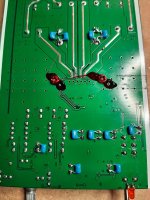
4) Bypass all 9 electrolytic caps around the op amps with 0.1uF
=> Cost 3.8E, gain under evaluation
NOTE: bypassing the middle one only gives already +1
5) Bypass the 3 470uF caps with each one 2.2uF cap, and the 100uF and 22uF ones with each one 0.1uF cap
=> Cost 3.4E, gain +1... you to decide if worth doing "while at it"...
6) Op amp PS, bypass each of the 2 op amp PS with 10uF and 0.1uF
=> 3.2E, gain under evaluation
Some mod rankings are under evaluation, but whatever you do you will end up with a sonic upgrade that is at least twice the step the widely acclaimed and massively perceived sonic step OPA1656 represents => Say a modded unit that works significantly better for 19$ material cost.
That process will be refined once all is comletely finalised... But guys, this is dead easy and cheap, so why don't give it a go and report on YOUR findings?
I hope this is of interest
Claude
This is still ongoing, but for those not confident with the soldering iron, not wanting to desolder anything, just playing with thin add-ons easy to do and undo, and keeping the casing, safety, functions etc. It is somethig I am considering for our 3rd amp, in hope to bring it to a satisfactory sonic level.
Total mod material cost is at Mouser's 19E WITH TAX...
Meaning the cost of a modded Aiyima with its PS is less than 85E!
The bypass caps used are all tiny Murata that all fit underboard and can be soldered either way (no polarity), either 10uF/25V or 2.2uF/50V "X7R type", or Murata 0.1uF/50V "C0G type". Links at Mouser below:
https://www.mouser.fr/ProductDetail/Murata-Electronics/RCER71E106K3A2H03B?qs=Zt%252BKPUOg4ofsQVPTPVDJLw%3D%3D
RCE5C1H823J2A2H03B Murata Electronics | Mouser France
RCER71H225K2A2H03B Murata Electronics | Mouser France
The recommended Op amp to fit is TI's excellent dual OPA1656:
https://www.mouser.fr/ProductDetail/Texas-Instruments/OPA1656IDR?qs=vLWxofP3U2ztlJVp%2BbIcnQ==
Mods are the following:
1) Resolder properly the output wiring to LS terminals
=> Cost 0, gain TBD
2) Replace the 2 removable OP amps with 2 x OPA1656 (these have to be soldered on adapters by you or any decent student)
=> Op amp cost 5.5E, gain +5
3) Big PS caps bypass, with each 2x 2,2uF (so 4 in total)
=> Cost 3.4E, gain +2
NOTE: for the same price you could go 4,7uF X7R + 0.1uF C0G, anyone wanting to give that combo a try?
4) Bypass all 9 electrolytic caps around the op amps with 0.1uF
=> Cost 3.8E, gain under evaluation
NOTE: bypassing the middle one only gives already +1
5) Bypass the 3 470uF caps with each one 2.2uF cap, and the 100uF and 22uF ones with each one 0.1uF cap
=> Cost 3.4E, gain +1... you to decide if worth doing "while at it"...
6) Op amp PS, bypass each of the 2 op amp PS with 10uF and 0.1uF
=> 3.2E, gain under evaluation
Some mod rankings are under evaluation, but whatever you do you will end up with a sonic upgrade that is at least twice the step the widely acclaimed and massively perceived sonic step OPA1656 represents => Say a modded unit that works significantly better for 19$ material cost.
That process will be refined once all is comletely finalised... But guys, this is dead easy and cheap, so why don't give it a go and report on YOUR findings?
I hope this is of interest
Claude
Last edited:
Hi Rob,
A while ago you asked about replacement potentiometer options... haven't fogotten that one, but it is not easy indeed.
We have yet to take the existing pot out to assess how good / bad it is - indeed, it doesn't look to good. Of course we went the easy way, read external pot, solves all the size issues...
Having said that, I had a look and if someone would have to retain an internal pot (convenient) the best bet is probably the very similar sized (and coloured) Alps. In fact it might be already an Alps pot inside the unit, or more probably... a fake/copy. That doesn't mean it is far worst though...
Would a genuine one, that as the same form factor, bring a benefit? Or a hand wired small Panasonic pot? I don't know, these aren't the best pot in the world and I wouldn't expect them to be a match to what is a benchmark for affordable pots, read Alps RK27 aka "Blue". And that one is no match by far to the Alps Black Beauty I own since decades, nor the Tocos I purchased recently, both competing indeed with VG stepped attenuators.
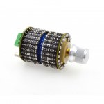
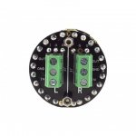
Now, thinking attenuators, there might be an option... Thanks to SMD and Chinese low cost, I found this 'DACT Type SMD stepped attenuator"
DACT Type SMD 21 Stepped Attenuator/Volume Control Potentiometer 10/20/100/250K | eBay
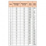
Of course it is a copy, but most people seem happy with it and the price is a steal. I don't even expect it to run on a par with the best potentiometers, but let's face it: if it turns out it is a match to an Alps blue than it is already a nice solution, provided you can live with 21 steps to adjust volume (it is not continuous and these are few steps).
NOW the biggest issue: SIZE.
My understanding is this part can't fit easily, but as you are a pro when it comes to making things fit with your experiments...
I would say the board needs to get out of the way, the pot needs to be fitted sideways (connectors to L or R) and the hole needs to be drilled to offset thevolume button to the top, to get a chance to have the right clearance. It is 21mm in diameter without connections and you can't of course run the risk to touch the SMD resistors underneath it. Better wrap the pot in case the screw gets lose.
Would that attenuator fit with all these adjustments? Not even sure, only trying can tell. For myself I don't know anything as qualitative in such a small foot print.
I hope this helps
Claude
A while ago you asked about replacement potentiometer options... haven't fogotten that one, but it is not easy indeed.
We have yet to take the existing pot out to assess how good / bad it is - indeed, it doesn't look to good. Of course we went the easy way, read external pot, solves all the size issues...
Having said that, I had a look and if someone would have to retain an internal pot (convenient) the best bet is probably the very similar sized (and coloured) Alps. In fact it might be already an Alps pot inside the unit, or more probably... a fake/copy. That doesn't mean it is far worst though...
Would a genuine one, that as the same form factor, bring a benefit? Or a hand wired small Panasonic pot? I don't know, these aren't the best pot in the world and I wouldn't expect them to be a match to what is a benchmark for affordable pots, read Alps RK27 aka "Blue". And that one is no match by far to the Alps Black Beauty I own since decades, nor the Tocos I purchased recently, both competing indeed with VG stepped attenuators.
Now, thinking attenuators, there might be an option... Thanks to SMD and Chinese low cost, I found this 'DACT Type SMD stepped attenuator"
DACT Type SMD 21 Stepped Attenuator/Volume Control Potentiometer 10/20/100/250K | eBay
Of course it is a copy, but most people seem happy with it and the price is a steal. I don't even expect it to run on a par with the best potentiometers, but let's face it: if it turns out it is a match to an Alps blue than it is already a nice solution, provided you can live with 21 steps to adjust volume (it is not continuous and these are few steps).
NOW the biggest issue: SIZE.
My understanding is this part can't fit easily, but as you are a pro when it comes to making things fit with your experiments...
I would say the board needs to get out of the way, the pot needs to be fitted sideways (connectors to L or R) and the hole needs to be drilled to offset thevolume button to the top, to get a chance to have the right clearance. It is 21mm in diameter without connections and you can't of course run the risk to touch the SMD resistors underneath it. Better wrap the pot in case the screw gets lose.
Would that attenuator fit with all these adjustments? Not even sure, only trying can tell. For myself I don't know anything as qualitative in such a small foot print.
I hope this helps
Claude
- Home
- Amplifiers
- Class D
- Aiyima TPA3251 Modification Build Thread!