")
the only question is can this amplifier module outperform amplifiers like Passlabs, krell, bryston, Balanced audio tech or any of these highend amps?
Measurably, probably yes. Audibly it should be just as good (apart from the ones that have been voiced on purpose to please some customers).
can anyone tell me which output mosfets have been used in this module?
so far everyone is showing the same dam pictures, no bottom side or close up shots of the daughter module and the IC's used. Can somebody show some alternative non marketing pictures please.
HalloMy Purifif amp uses the Eval board for the input stage and sounds great-mostly it just sounds like whatever DAC i pair it with.
I like to tinker though, and am considering replacing the OPA 1612 with the discrete Sonic Imagery 994s. These discrete OPAs appear to match the specs of the 1612, except for current availability, which is way higher. I am actually a believer in having much more current available than "needed", and feel this often results in sonic improvements, maybe I'll try it. I would probably also provide +/- 18 VDC rails for the 994s directly from my +/- 18 VDC supply in the amp.
It would be realy nice if you keep us informed during your " Sonic Imagery 994s" tests.
Thank you
There is no disassembly of the underside of the Purifi 1et400a modules or part detailed number details used. Some of us not only use Google but actually make announcement of non existent results so Google will have them for the next person.
Ok, your initial question was a bit ambiguous though. As for "inside of those amps" I could have linked again the gallery of my build but it was not clear you wanted the innards of the Purifi modules.
Parts
There are no magical parts involved in the performance of the Purifi Amplifiers. these amps work the way they do because of design considerations and the maths involved with their development. The parts are fairly ordinary, but it is the extraordinary genius of Bruno Putzeys' development which makes the amplifiers special.
If you are really interested in learning about these amps, there are quite a few interviews with Mr. Putzeys regarding their design, as well as some technical descriptions at the Purifi website. You can find all of these with a few minutes of Googling.
My Purifi Stereo Amplifier Build
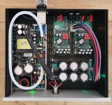
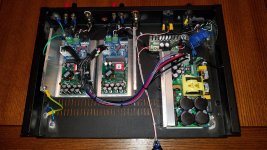
So here is my not-quite-finished implementation of a stereo Purifi amp build.
There is more involved in putting one of these together than I expected. A lot more time was spent figuring out the layout and the penetrations pattern than I thought would be necessary. Then there are the little details concerning connectors and such.The connections to the amps themselves ended up being the easiest part.
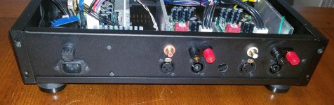
I made all the penetrations in the back panel myself using a punch and a hand-held drill. I would probably pay to have this done at a machine shop if I were to do it again. The job I did is acceptable, but far from perfect. It would have been a lot easier to add my fittings to a pre-cut panel, and since I already had the drawing it would have been trivial to have this done professionally.
I spent one evening listening to the amp in its current state: No disappointments--the upper-register detail is to me the stand-out improvement, but everything else sound very solid as well. For that listening I was connected directly to my TEAC NT-505, but in future I will be feeding it with my Emotiva AVR pre-amp.
The parts not yet complete are:
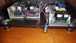
The Neurochrome buffers are well thought out, and documentation is extremely good. With these I don't have to worry about soft start, or auto-shutoff in case of high DC, and things like this as they take full advantage of capabilities of the Hypex power supply.
For making the power Y connector between the two buffers and the single PSU I first soldered the pairs of wires from the two buffers after zip-tying them together, then I soldered the appropriate PSU wire to the joined pair. I covered the solder joint with shrink wrap.
I have not yet decided if I need to connect the remote sensing to the speaker post--it's hard to imagine it will make much improvement given the fact that they are already routed to the Neurochrome outputs, and the short connection between those outputs and the speaker binding posts on the amp. I am not considering a connection all the way to the speaker.
I have purchased the Neurochrome external regulator boards, but haven't installed them yet. I will at some point but am not sure I will hear a difference. For now I want to start enjoying my amp as soon as possible.
Ron
So here is my not-quite-finished implementation of a stereo Purifi amp build.
There is more involved in putting one of these together than I expected. A lot more time was spent figuring out the layout and the penetrations pattern than I thought would be necessary. Then there are the little details concerning connectors and such.The connections to the amps themselves ended up being the easiest part.
I made all the penetrations in the back panel myself using a punch and a hand-held drill. I would probably pay to have this done at a machine shop if I were to do it again. The job I did is acceptable, but far from perfect. It would have been a lot easier to add my fittings to a pre-cut panel, and since I already had the drawing it would have been trivial to have this done professionally.
I spent one evening listening to the amp in its current state: No disappointments--the upper-register detail is to me the stand-out improvement, but everything else sound very solid as well. For that listening I was connected directly to my TEAC NT-505, but in future I will be feeding it with my Emotiva AVR pre-amp.
The parts not yet complete are:
- wiring to the Speakon connectors--As soon as I make some better quality speaker cables with Speakon ends I will be using these in lieu of the banana plugs.
- Wiring to toggle for SE vs. Balanced input -- the toggle will short the balanced "-" to ground in the case of SE source. But in practice I will be feeding the amp with a balanced source.
- I already wired up the cool LED switch, but need to have the .75" hole drilled in the 10mm Aluminum front panel for mounting this switch.
The Neurochrome buffers are well thought out, and documentation is extremely good. With these I don't have to worry about soft start, or auto-shutoff in case of high DC, and things like this as they take full advantage of capabilities of the Hypex power supply.
For making the power Y connector between the two buffers and the single PSU I first soldered the pairs of wires from the two buffers after zip-tying them together, then I soldered the appropriate PSU wire to the joined pair. I covered the solder joint with shrink wrap.
I have not yet decided if I need to connect the remote sensing to the speaker post--it's hard to imagine it will make much improvement given the fact that they are already routed to the Neurochrome outputs, and the short connection between those outputs and the speaker binding posts on the amp. I am not considering a connection all the way to the speaker.
I have purchased the Neurochrome external regulator boards, but haven't installed them yet. I will at some point but am not sure I will hear a difference. For now I want to start enjoying my amp as soon as possible.
Ron
Attachments
- Home
- Amplifiers
- Class D
- Brainstorming Purifi 1et400a amps