JMF11, I very first time downloaded tas3251.pdf today before lunch and reading through. The datasheet contents all registers list etc, usually, that is enough to start a project. What kinda extra info you may need?
lutkeveld, I really have no idea what you talking about but TAS5558 allow to update any biquad any time(my app dynamically allocate biquads for parametric EQs ether LPF/HPF 12 or 24db/oct), the only problem seems Ti invented for themselves Fs synced DSP update(to avoid clicks, AD inc. calls that "safe load" mode) in 2018 and that indeed implemented in the TAS3251.
My experience is with the TAS5754M, which uses purepath console 2. Maybe it changed in PPC3. If anyone has used PPC3, please correct me if I am wrong.
With previous devices it was only possible to figure out which biquads were linked to which registers by changing a biquad in the GUI and comparing the register dumps. TI does not provide the registers of the biquad coefficients (or other DSP filters for that matter).
This makes a biquad app more difficult, but not impossible.
Also, you first need to enter powerdown before changing any DSP filter settings. But that can be done in ~300mS so almost instantaneously.
But again, I have not fully read all documents regarding the TAS3251, so I could be wrong. I only have experience with older generation devices.
if it so, that's why AD inc and their Sigma DSPs won )) And because of "comprehensive" support as well. I'm asking and waiting for the answer whole August )) TAS5558: TAS5558 Energy Manager Averaging coefficients - Audio Amplifiers Forum - Audio Amplifiers - TI E2E Community
Last edited:
That is exactly true!
It is not that big of an issue when you are a manufacturer, because you can copy your settings over thousands of products. However, for the DIY market where people want to experiment without spending a lot of money and time, SigmaStudio is the clear winner.
If TI publishes the register maps (or somebody reverse engineers it) it should be possible to make a GUI like SigmaStudio which can change parameters real time. Or some other way to use PPC3 without the EVM.
That would be ideal for the DIY community; hooking up a TAS3251 board via USB, figuring out the wanted parameters and then programming the microcontroller with the header file so it can run stand-alone.
@TNT
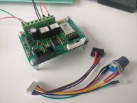
I made a PCB based on the TAS5754M that will be released in the near future:
-DSP (biquads, smoothclipping, bass enhancement, limiters etc)
-2x40W or 1x80W class D amplifier
-Bluetooth v4.2 class 1 module
There are some early versions being tested by early adopters and it looks very promising. Once I am ready to sell I will make a dedicated thread. Do not ask too much questions in this thread, I do not mean to hijack this. More so to show what is possible with these kinds of chips.
Attachments
JMF11, I very first time downloaded tas3251.pdf today before lunch and reading through. The datasheet contents all registers list etc, usually, that is enough to start a project. What kinda extra info you may need?
For me, it is not (yet) complete: I do not see the registers to configure the biquads, and other functions from section 8.5.1 about the DSP programming.
There are a lot about the PLL config, DAC contro, volume. But it seems to me that they are not all here, unfortunately.
JMF
But looking at the datasheet, I much prefer the newer TAS3251. The quite high distorsion at 4k I think might be troublesome and the corresponding peak is much lower in level and also higher in frequency. But I like the format of your board lutkeveld.
//
//
Or even the TAS5768M for that matter, which is the next gen brother. I have been developing this board for almost 2 years now (started with almost no knowledge on PCB design) so in the meanwhile there are some newer options, but it's still a great chip.
So, as of discussions here: TPA3255 - all about DIY, Discussion, Design etc., my idea is NOT to include the PFFB in this design.
This will help keep the circuit simple (suppress 24 items from the BOM), keep a suitable gain (as raised by IVX), without compromising the performance if the output inductors are selected carefully.
JMF
This will help keep the circuit simple (suppress 24 items from the BOM), keep a suitable gain (as raised by IVX), without compromising the performance if the output inductors are selected carefully.
JMF
Good strategy. Me, I wold like single (L / R) channel operation via Toslink.
//
My idea here is modularity, with a I2S input, which is so versatile and rarely exposed in other products. It is easy to add a Toslink=>I2S module on top.
However, my thinking is that, especially for active amplification of multiway speakers, Asynchronous USB input to a module with a good clock and I2S output is a very good option. And a basic microcontroller can do that, and control the I2C config of the TAS3251.
This will be my way.
JMF
 Good!
Good!@TNT
I made a PCB based on the TAS5754M that will be released in the near future:
-DSP (biquads, smoothclipping, bass enhancement, limiters etc)
-2x40W or 1x80W class D amplifier
-Bluetooth v4.2 class 1 module
There are some early versions being tested by early adopters and it looks very promising. Once I am ready to sell I will make a dedicated thread. Do not ask too much questions in this thread, I do not mean to hijack this. More so to show what is possible with these kinds of chips.
It is better to orient the MLCC with their long body side to the shorter pub side to minimize piezoceramic effects and possible stress which may result in cracks. For your shown design this would mean the MLCC around the TAS need to be rotated by 90 degrees. You may also thing about adding an additional center mounting hole to break up the mechanical „plane“. Doing wrong can directly couple into the audio path by piezoceramic modulation. (i.e. knocking onto the board) This is also valid if ceramics are used in voltage bias nets.
So, as of discussions here: TPA3255 - all about DIY, Discussion, Design etc., my idea is NOT to include the PFFB in this design.
This will help keep the circuit simple (suppress 24 items from the BOM), keep a suitable gain (as raised by IVX), without compromising the performance if the output inductors are selected carefully.
JMF
I’d suggest implementing the „1 capacitor feedback“. This doesn’t need an extra snubber as it only corrects risetime/signal-response and can avoid excessive ringing with unloaded outputs. Footprint 0805 is fine to fit almost anything. Only a few picofarrats are needed if i remember voltwide correctly. Fort his to work an NTC is needed for the output snubber. (which is troughhole)
If you want to implement PBTL i’d suggest doing it before the output filter as this gives lower THD but needs inductors with more unsaturated currant handling.
Last edited:
When moving electronics (and oscillators!!!) closer or inside speakers, vibration in immunity becomes extra important.
//
//
It is better to orient the MLCC with their long body side to the shorter pub side to minimize piezoceramic effects and possible stress which may result in cracks. For your shown design this would mean the MLCC around the TAS need to be rotated by 90 degrees. You may also thing about adding an additional center mounting hole to break up the mechanical „plane“. Doing wrong can directly couple into the audio path by piezoceramic modulation. (i.e. knocking onto the board) This is also valid if ceramics are used in voltage bias nets.
I understand your point, but rotating the caps would make layout more difficult and I doubt it would have a large effect, especially on such a small pcb. But maybe I'm underestimating it...
What do you mean by 'breaking up the mechanical plane'? Add an extra mounting hole to reduce flex in the middle?
Correctly.
We examined the influence of piezoceramic effects on a 1.0mm 35x50mm pcb with a TPA3128 which had MLCC as coupling caps and for local AVDD decoupling. Knocking onto the PCB clearly showed a influence on the lower frequency band up to 500Hz. It also where clearly hearable from the output of the speakers. If mounted into an 400 liter basshorn, there was an echo/effect like effect. So yes, flexing does have a signature impact on sound if mounted wrong or having insufficient mechanical decoupling. I can search for the plots if there's interest.
We examined the influence of piezoceramic effects on a 1.0mm 35x50mm pcb with a TPA3128 which had MLCC as coupling caps and for local AVDD decoupling. Knocking onto the PCB clearly showed a influence on the lower frequency band up to 500Hz. It also where clearly hearable from the output of the speakers. If mounted into an 400 liter basshorn, there was an echo/effect like effect. So yes, flexing does have a signature impact on sound if mounted wrong or having insufficient mechanical decoupling. I can search for the plots if there's interest.
- Home
- Amplifiers
- Class D
- [design log] Neat 2x170W I2S in, I2C controlled, integrated DSP amp (TAS3251)