I’d suggest implementing the „1 capacitor feedback“. This doesn’t need an extra snubber as it only corrects risetime/signal-response and can avoid excessive ringing with unloaded outputs. Footprint 0805 is fine to fit almost anything. Only a few picofarrats are needed if i remember voltwide correctly. Fort his to work an NTC is needed for the output snubber. (which is troughhole)
If you want to implement PBTL i’d suggest doing it before the output filter as this gives lower THD but needs inductors with more unsaturated currant handling.
Thanks for the advice Doctormord
In parallel, I was looking at the different components of the power supply stage of the TPA3251EVM, TPA3255EVM and TAS3251EVM.
I notice that the LM5010 exists in HTSSOP package, but has a downward thermal pad. This is I imagine difficult to handle for hand soldering. Would there be some more suitable option for hand soldering, with similar performance?
Best regards,
JMF
I notice that the LM5010 exists in HTSSOP package, but has a downward thermal pad. This is I imagine difficult to handle for hand soldering. Would there be some more suitable option for hand soldering, with similar performance?
I use LM5007, 5008
I use LM5007, 5008
LM5007 seems to do the job, from V and I and I perspective.
It seems that the TAS3251 draws typically 90 mA from the 12V. The LM5007 can deliver up to 700 mA.
Thanks !
JMF
Hi JMF11,
Here are two documents I found very useful starting then progressing with Kicad.
First one is a ham radio club project, it’s very basic but it allows me, step by step, to understand the various Kicad module and the whole design process then to be able to start at new project from scratch.
Second one, from Dave Jones founder of EEVBlog, give you very practical and useful insights on the way to design a pcb.
Those two docs are not recent but, with the help of Kicad documentation and some practice, I’m know working on 4 layers projects...and i’m still progressing!
Hope you’ll find those docs useful, I follow your threads with attention as I’m also using STM32 in my projects.
Chris
Link to First doc : https://www.robertponge.com/telechargements/ebooks/kicad-2.pdf
Hi AIM65,
I'm finishing the reading of the PCB design tutorial and it is very instructive and well done. It helps grasp the basics, which is really important. A valuable reference for me !
JMF
I notice that the LM5010 exists in HTSSOP package, but has a downward thermal pad. This is I imagine difficult to handle for hand soldering. Would there be some more suitable option for hand soldering, with similar performance?
MP2459:
https://www.monolithicpower.com/pub/media/document/MP2459_r1.01.pdf
It's pin-compatible (need pullup on /EN) with the TI LMR16006 at half the price with a bit lower switching frequency. I used LMR16006(Y) in the past at 700kHz and 2.1MHz without issues. Actually i use the MP2459 with my LTC3784 4-phase boost-converter.
Please Doc, show tbe graphs!
//
Ok ok.
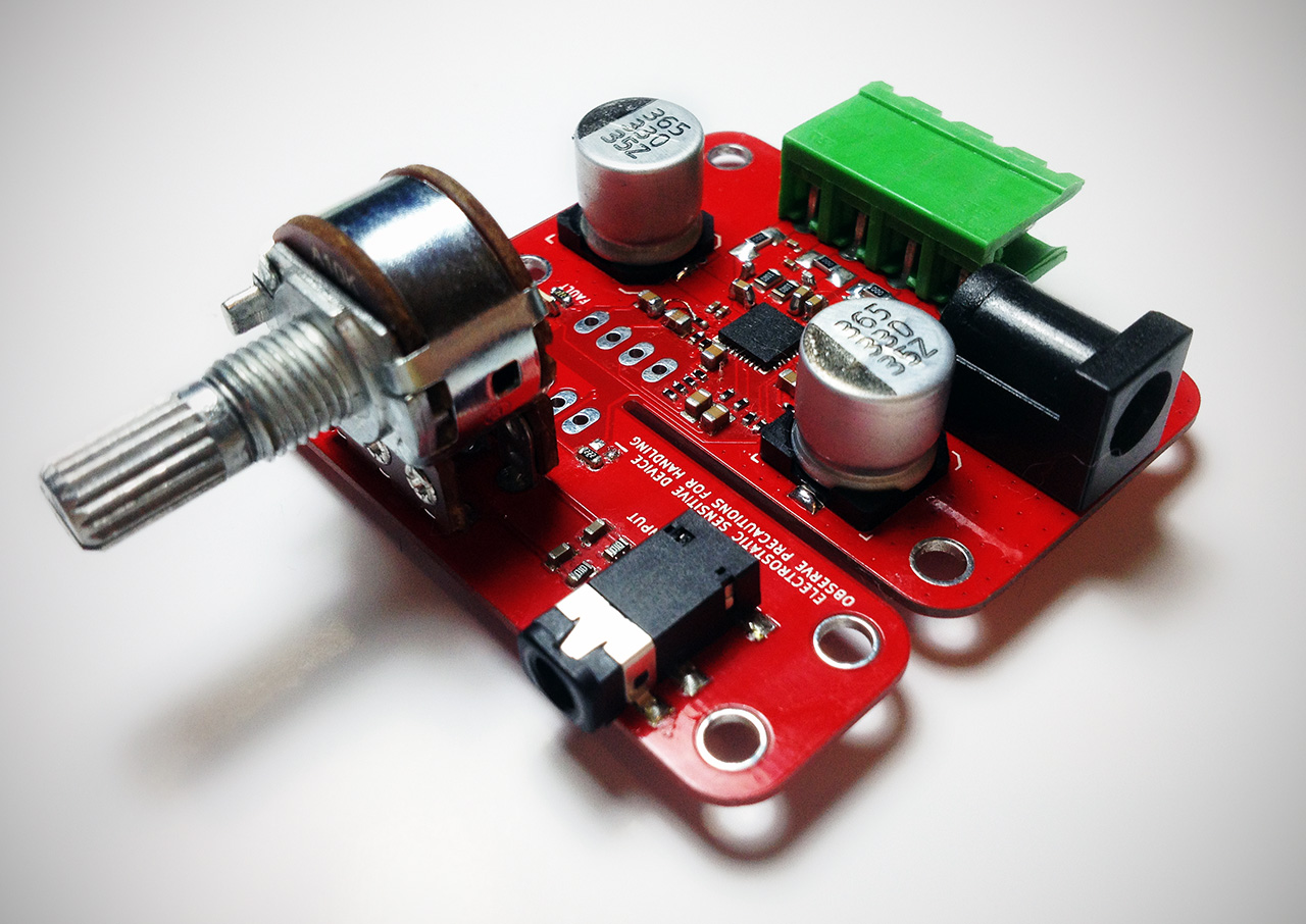
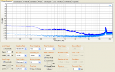
Here's the results for the TPA3128 on a 1.0mm board when knocking at the side edge of the PCB with some Murata 2u2/25V MLCC in place (input coupling):
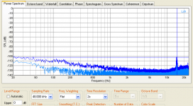
We then modified the mounting to vertical mounting like so that the MLCC is standing like a tombstone on one pad and is then wire-connected to the other pad. The resulting improvement is shown here:
As already written above, the mechanical influence can be reduced when mounting the MLCC with their long body side to the short side of the board. It is a good practice to keep this in mind when using MLCC. As a side-effect/benefit, flex-cracking-risc is much lower when doing so. (For the latter, flex/soft-termination-caps might help as well.)
The device under test:
Attachments
Skip switching converters and use a higher feed + passive converters I instead. There is enough hf to battle anyways!
?
//
?
//
Ok ok.
Here's the results for the TPA3128 on a 1.0mm board
Correction: It's the TPA3132D2 on the board, not the TPA3128.
Skip switching converters and use a higher feed + passive converters I instead. There is enough hf to battle anyways!
?
//
Why? Voltwide and i use the LM5010 without further LDO filtering for the AVCC stage and theres no degradation in THD but YMMV. Having problems with HF is mostly due to improper grounding loops and PCB layout.
Last edited:
X7R?some Murata 2u2/25V MLCC
PS: Just tried to knock my HiFi-TOY PCBA - no effect at all, S/N steady stay -104db(A). that's why I like "Power DAC" topology 😉
X7R?
PS: Just tried to knock my HiFi-TOY PCBA - no effect at all, S/N steady stay -104db(A). that's why I like "Power DAC" topology 😉
No, Y5V 🙄 .. Of course X7R.
Sounds like everything you do is always better than the others..

it is not what I did, I talking about native Ti chipset TAS558+TAS5624, so Ti did that immunity for piezo caps. I believe it is because Ti used silicon capacitors for the loop filter, aka noise-shaper, together with I2S it gives excellent immunity.
[Resolved] TAS3251: "Ultra-HD" Where is 192KHz support? - Audio Forum - Audio - TI E2E CommunityTAS3251: "Ultra-HD" Where is 192KHz support?
hence, for high-resolution audio ability need to add external sample rate converter IC(and EVB has it!). I quickly losing my exciting regarding TAS3251..
The TI answer is ok I believe "The ultra HD was in reference to the THD+N and SNR performance" as these 2 parameters has much more influence of perceived resolution than the fs.
//
//
hence, for high-resolution audio ability need to add external sample rate converter IC(and EVB has it!). I quickly losing my exciting regarding TAS3251..
I had seem that. However as my music is 99.9% 44k, this is fine for me. In my current config, my music server (mpd on Linux, in an OrangePi) has the ability to perform the sampling rate conversion. This is working very well.
Is there really 192 kHz music available yet ? I will develop a new project when it will be available 🙂
- Home
- Amplifiers
- Class D
- [design log] Neat 2x170W I2S in, I2C controlled, integrated DSP amp (TAS3251)