TPA3255 consumtion
at post #548 FF is calculating the consumption
12V/ 44mA (typ.) for the TPA3255 chip GVDD input. Digital circuit consumption.
12V/ 30mA (typ.) for the TPA3255 chip VDD input. Digital circuit consumption.
i found in the datasheet
IGVDD_X "Gate-supply current per full-bridge
44mA
IPVDD_X "PVDD idle current per full bridge
24mA
so 44mA *4 because of 4 bridges??? = 44mA*4= 176mA
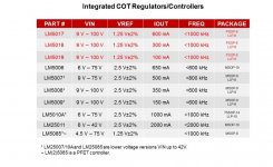
LM5017 (100V input) - and there exist cheaper ones for less input voltage.
Have a look at parametric search (mouser, digikey...) to find them.
the new one with COT = constant on time ......Vref 1,25 are just up to 600mA = LM5017..
stronger... Vref:2,5V, 1000mA LM5010A
Attachments
Last edited:
the new one with COT = constant on time ......Vref 1,25 are just up to 600mA = LM5017..
stronger... Vref:2,5V, 1000mA LM5010A
Do you really need 1000mA? If not, a weaker chip makes more sense. Because the saturation current of your inductor should always be equal or bigger than the peak current limit of the regulator.
Do you really need 1000mA? If not, a weaker chip makes more sense. Because the saturation current of your inductor should always be equal or bigger than the peak current limit of the regulator.
actaully an amp is running in 8R config..with 150mV rms in(that realistic for long term listening) my lab psu shows 0,6A current at 28V consumption....i didn´t measure the consumption of the opamps or TPA chip...where could i do that?
actaully an amp is running in 8R config..with 150mV rms in(that realistic for long term listening) my lab psu shows 0,6A current at 28V consumption....i didn´t measure the consumption of the opamps or TPA chip...where could i do that?
sorry not correct. it was the 4R board..and other input
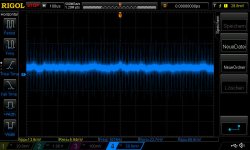
now the correct values:
28V psu, 8R load, input 200mVrms sweep with 10Hz- 35kHz...., this is a sound level whch is in my room enough...it measured it...post before...
consumption shows 400mA at max.
Vpp at max is 18V
Power pp= Vpp^2 / 2 *R for each channel
P pp= about 21Watt per channel
so yes 600mA should be ok for home use
thank you voltwide

at post #548 FF is calculating the consumption
12V/ 44mA (typ.) for the TPA3255 chip GVDD input. Digital circuit consumption.
12V/ 30mA (typ.) for the TPA3255 chip VDD input. Digital circuit consumption.
i found in the datasheet
IGVDD_X "Gate-supply current per full-bridge
44mA
IPVDD_X "PVDD idle current per full bridge
24mA
so 44mA *4 because of 4 bridges??? = 44mA*4= 176mA
please can you have a look at that?
")
thx
...input observation
pic 1
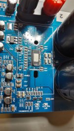
i checked the red colored cap directly after the power supply terminals. it is a Evercon 47µF / 63V . ESr shows at 1kHz and 10kZ about 400mOhms ESR..so i changed it!!
this board is running a lot of hours so the caps is not from stock.
pic 2 directly on pin 4 at the regulator of my amp board
i use now my only value what i have in stock...nichicon fine gold 220µF/100V..and its running since yesterday under load (burn in) because this caps i bought 1 year ago.
pic 1
i checked the red colored cap directly after the power supply terminals. it is a Evercon 47µF / 63V . ESr shows at 1kHz and 10kZ about 400mOhms ESR..so i changed it!!
this board is running a lot of hours so the caps is not from stock.
pic 2 directly on pin 4 at the regulator of my amp board
i use now my only value what i have in stock...nichicon fine gold 220µF/100V..and its running since yesterday under load (burn in) because this caps i bought 1 year ago.
Attachments
I understood you are looking for a 12V-regulator as aux supply for the TPA - not as a supply for the hole power bridge circuit?!sorry not correct. it was the 4R board..and other input
now the correct values:
28V psu, 8R load, input 200mVrms sweep with 10Hz- 35kHz...., this is a sound level whch is in my room enough...it measured it...post before...
consumption shows 400mA at max.
Vpp at max is 18V
Power pp= Vpp^2 / 2 *R for each channel
P pp= about 21Watt per channel
so yes 600mA should be ok for home use
thank you voltwide
at post #548 FF is calculating the consumption
12V/ 44mA (typ.) for the TPA3255 chip GVDD input. Digital circuit consumption.
12V/ 30mA (typ.) for the TPA3255 chip VDD input. Digital circuit consumption.
i found in the datasheet
IGVDD_X "Gate-supply current per full-bridge
44mA
IPVDD_X "PVDD idle current per full bridge
24mA
so 44mA *4 because of 4 bridges??? = 44mA*4= 176mA
please can you have a look at that?
thx
Hi Chris,
I should have read the specifications more carefully.
TPA3255 has four half-bridges and they are coupled as two full-bridges (BTL).
VDD is a 12V supply.
GVDD_x is a 12V supply as well.
PVDD is from the raw supply voltage and not regulated.
We are only concerned with the regulated supply voltages as the raw supply voltage has anyway a capacity of several Ampere.
IVDD is 30mA (typical). It seems to be for the whole chip.
IGVDD_x is 44mA per full-bridge (I overlooked that). With two full-bridges (each made from two half-bridges) the total should be 88mA (typical).
IPVDD is not considered because it is not a regulated voltage.
Adding 30mA and 88mA leaves a result of 118mA (typical). Considerably more than my first estimation. Now I know why my linear regulators get quite hot with the OP-AMP (2xOPA2134) current on top.
118mA is "typical". Design for 150mA "worst case". Add the OP-AMP current "worst case" if this current is drawn from the same 12V supply rail.
Last edited:
Good morning Voltwide
Good morning FF
thank you both.
i want to clarify 2 things:
1. what is a realistic power consumption. thank you FF
TPA3255 has four half-bridges and they are coupled as two full-bridges (BTL).
i am still a noob
2. yes i am looking now more what a good regulator is doing...thank you voltwide
chris
Good morning FF
thank you both.
i want to clarify 2 things:
1. what is a realistic power consumption. thank you FF
TPA3255 has four half-bridges and they are coupled as two full-bridges (BTL).
i am still a noob
2. yes i am looking now more what a good regulator is doing...thank you voltwide
chris
..update...
Hi agian
After some listening test i decided to change my last ace
After checking some original decoupling caps i i get strange values:
the original caps a used at the beginning of my journey so no excusse that they are long stored. the values are @120HZ Sanwah 4700µF(63V
C=4178µF......detha: -85,6°, D=0.260, Q:5,83, ESR = 0?!
I have no idea why they have no ESR shown
I put all caps out!.....i use now doctor´s magic caps
Chemicon 661-EGPD630E242MM40H.
after some hours burn in the boards are more quiet and sounds much better. for 4 ohms configuration.
finally i found some KEMET low ESR 220/50V to change the caps directly at the terminals. this is the first cap before regulators
i am near to the finish line for modding now. the boards opa1602 or AD8599 are as near as possible to the compared board 3251EVM. to be honest ...I really like the sound of the OPA1602.
the 3251(NE5532) is more gentle and the AD8599 is slightly more pushing some vocals but with a very nice hard onset of some guitares...etc
all boards are not modded with AVDD or other low noise regulator, or supply voltage split
Last edited:
How about Panasonic EEU-FS ? the latest series of panasonic , featuring ultra-low ESR Long Life (Up To 10,000 Hours at 105°C) And A Wide Temperature Range (-40°C to +105°C). Smoothing Power Output.
Do you think it's better than FC?
Hi Ferdie
i don´t know the panasonic:
i pic up some caps from the previous posts the last 8 month
Nichicon UHW1J222MHD
Nichicon UHE1H102MHD6
Chemicon EKZN630ELL222MM40S
Panasonic EEU-FC1H152L
Epcos (TDK) B41858C6278M000
Chemicon 661-EGPD630E242MM40H
about 1800µF/and 50V -63V with low esr 20mOhms and high ripple current is mandatory.
chris
How about Panasonic EEU-FS ? the latest series of panasonic , featuring ultra-low ESR Long Life (Up To 10,000 Hours at 105°C) And A Wide Temperature Range (-40°C to +105°C). Smoothing Power Output.
Do you think it's better than FC?
They are pretty much the same, just downsized for 1 size. Ripple current rating is a bit lower for the new FS compared to FR.
The cam is a fake?just to share my chinese board with new op amp opa2132ua & new LM2575HVS

The cam is a fake?
could be...
but with my Sams...A5 /2016 its maybe worse....@Ferdie
use more light and use the HDR modus of your smartphone and it will be nice pics...
thanks
just to share my chinese board with new op amp opa2132ua & new LM2575HVS
Hi FerChin79
The amp has a very good (strong) GAIN - its about 27dB so with about 150-250mV input it is loud for living rooms.
so there is no need to solder the input of your source to the amp. you can use normal RCA connectors directly .
symmetrical input = XLR is not possible at this board.
Which speakers are you using?...the output filter in this BTL config is normally about 12µ H(12,4-13µH) and 1µF. so its set to a more likely 8ohm speaker configuration.
awaiting your pics...and more details
chris
- Home
- Amplifiers
- Class D
- What is wrong with TPA3255?