From the little info i found online so far, sounds like:
100AS1 uses TPA3251
200AS1 uses TPA3255
200AS2 uses TPA3255
they have a bunch of others AS boards…
Seems pretty convenient with the power supply on the board already. I would imagine it’s pretty good sounding and good quality too
100AS1 uses TPA3251
200AS1 uses TPA3255
200AS2 uses TPA3255
they have a bunch of others AS boards…
Seems pretty convenient with the power supply on the board already. I would imagine it’s pretty good sounding and good quality too
Hi, sorry to interject myself and my question in your current discussion...
I'm aiming to build a pair of active 3-way speakers; each driver getting its own TPA3255 amplifier, all filtering duties done by DSP.
So - first I'm building a "test" setup.
I've bought 2 TPA3255 amplifier boards from 3E audio - one single channel 480W, one dual channel 260W - and for filtering the 3E audio DSP board.
But now I found out the 3E Audio DSP board has 1.0Vrms input while my Google Chromecast Audio has 2.0Vrms output.
I haven't wired anything up yet but I assume connecting the 2.0Vrms Chromecast output to the 1.0Vrms input of the 3E Audio DSP would lead to clipping.
So - how to get my 3E Audio setup to accept my Google Chromecast output without clipping?
According to the ADAU1701 datasheet the ADAU1701 can be configured to accept 2.0Vrms by replacing a resistor with an 18Kohm one.
I've emailed 3E Audio who confirmed replacing that resistor should work.
But I can't figure out which resistor that would be on the 3E Audio DSP board..
Any help here would be appreciated!
Last edited:
So they said it could be done, then forgot to show you where or how? maybe reply to email reminding them that they must have missed sending an attachment or something…
DC offset TDA3255 3e Audio (Crossover resistor heating up)
I just finish a pair of Zaph SR71 speakers however I noticed the cabinet around the area of the crossover was getting quite warm. This happened while playing music but also when the amp was on but no music playing.
So I Googled and discovered heating up the padding resistor can happen while playing music loudly tho this was loud or quiet, no difference. Anyway left it at that.
Then I changed my existing amp (TDA3255 using the 3e-Audio board) to another D class, this one from Connex Electronic based around the IRS2092S driver chip. I was amazed to find the speaker now remain stone cold, not even a hint of warming up.
I would love to find out why this is happening for one amp and not another, does anybody have any ideas what is going on here.
Cheers
BTW love the speakers and the Connex amp, sound great together.
A thought occurred and I just measured the DC offset of the TPA3255 outputs. One was 1.4v, the other 2.7v. EEk! guess I'll refer this to the amplifier gurus.
Don't you hate it when you answer your own queries?
Don't you hate it when you answer your own queries?
DC offset on output.
Am using a TPA3255 board from 3e-Audio. I recently finished a new set of speakers and found the cabinets heating up around the crossover, from my reading assume its the tweeter padding resistor.
Changing amps recently found the heating did not occur with the new amp. I checked DC offset on outputs of the TPA3255 - one was -1.4v, the other -2.7v. I am sure this will account for the resistor heating up which occurred even without music but amp on. The offset is present with or without input connected.
So any idea what would cause this? Do I have a sick amp?
Last edited:
 Posts moved to this thread.
The parts of the tweeter network should not be affected by DC, as there has to be a capacitor to prevent it from burning up. A capacitor does not conduct DC, so it does not heat up from that in the high pass.
It may be an oscillation problem of your amps that has nothing to do with the DC.
If you designed the x-over by your self, that may be a factor...
On the other hand, an amplifier producing 2.7 V offset is defektive, just as one with 1.4 V.
This DC will heat up the bass voice coil and imbalance the suspension. Depending on your speakers you can ruin them using them this way.
Post high quality pictures of your amp build, there may be something wrong with it.
If you blame it on the amp, having DC offset from the beginning, good luck. I have some experiance with that.
3e-Audio usually does not react amused or pay much attention if have any warranty claims or questions.
From 3e you usually get useless answers not dealing with your problem. I still did not find out whether they do not understand English or don't want to.
Usual answer: We test any single item we sell. Each one for many days in our private living room, so it worked 100% when we sent it to you.
You Dummy broke it.
This is a normal behavior with our Chinese friends, they are the worlds nicest people when they want to sell something and go surprisingly silent when you have any after sales questions. If you can live with that, you are fine.
Last edited:
Thanks Turbowatch.
The speakers are SR-71 designed by Zaph Audio, the tweeter padding resistor is ahead of the cap in this crossover (unusual I think) so guessing it can still be affected by DC. The bass units are fairly robust with healthy XMAX so I am fairly hopeful they are not damaged but I take your point.
But as you say the offset means the amp is defective, I wouldn't have bothered contacting 3e and what you cay kinda confirms it would be a waste of time. So I think I will bin the amp board and reuse the chassis and PS.
Cheers
Quick question.
My power supply comes out at 53.5v, Based on the trafo (36v) I was aiming for 50v but the local mains voltage is a bit high.
Anyway would the higher voltage be an issue? According to the datasheet for the chip its within spec but.....
My power supply comes out at 53.5v, Based on the trafo (36v) I was aiming for 50v but the local mains voltage is a bit high.
Anyway would the higher voltage be an issue? According to the datasheet for the chip its within spec but.....
OK, I supposed you had the recomanded 3e power supply? You don't have 36V but 53.5V?
That is some serious overvoltage. Makes an 300W amp an 600W monster...
Don't bin it right now, maybe 3e-Audio has improved. Miracles happen. Just don't switch on your amp any more. If it is not toast yet, it comes closer to becoming it with any start. Even a fridge turning on could kill it.
No picture? You don't want to give secrets of your high end installation?
Can you post a link to the x-over schematic? From your answer I suppose you have not really understood how an x-over works.
Well the 3e site says max voltage 51v which is what I was aiming for. The PS caps on the 3e board are rated 63v and the chip states 53.5v as typical and 56.5v max for a 6 ohm speaker such as mine. So I didn't see this a overvoltage.
Link to crossover - http://www.zaphaudio.com/SR71-crossover.gif
I'll get a pic tomorrow (getting late here) but its nothing special, just regular trafo/bridge rectifier/CLC supply.
Link to crossover - http://www.zaphaudio.com/SR71-crossover.gif
I'll get a pic tomorrow (getting late here) but its nothing special, just regular trafo/bridge rectifier/CLC supply.
TPA3251 amp
Hi!
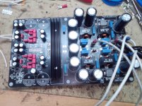
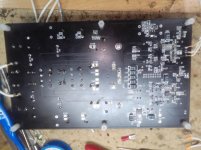
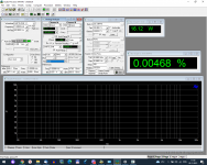
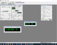
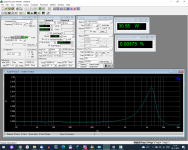
It's my variant amp on TPA3251 (BTL mode). 24V power supply, 30W output power.
Balanced/unbalanced 2Vrms input.
Hi!
It's my variant amp on TPA3251 (BTL mode). 24V power supply, 30W output power.
Balanced/unbalanced 2Vrms input.
Attachments
-
 IMG_20211129_120904.jpg836.7 KB · Views: 507
 -
 IMG_20211129_120949.jpg742.4 KB · Views: 471
 -
 CCIF.png117.6 KB · Views: 423
 -
 DIM 30.png115.8 KB · Views: 398
 -
 DIM B.png117.5 KB · Views: 383
 -
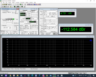 noise.png115.9 KB · Views: 209
 -
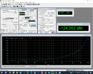 noise vs freq.png118.4 KB · Views: 211
 -
 SMPTE.png116.6 KB · Views: 207
 -
 THD+N.png125.6 KB · Views: 200
 -
 THD+N vs freq.png124.8 KB · Views: 316
Well the 3e site says max voltage 51v which is what I was aiming for. The PS caps on the 3e board are rated 63v and the chip states 53.5v as typical and 56.5v max for a 6 ohm speaker such as mine. So I didn't see this a overvoltage.
Link to crossover - http://www.zaphaudio.com/SR71-crossover.gif
I'll get a pic tomorrow (getting late here) but its nothing special, just regular trafo/bridge rectifier/CLC supply.
Hi!
Although the IC datasheet says that it CAN work with 51V, in my opinion, it does not mean that this voltage SHOULD be used in most situations since it makes the IC work close to the theoretical limit.
How many Ohms are your speakers?
Look, I have a 3e Audio working with a 48V source set to 46V. I use 6 Ohm speakers and I don't have heating on the crossover components and neither this high level of DC on the outputs.
I have two other generic boards with TPA3355, but in Mono configuration and with them I don't have any problems either.
It's worth doing the test with a lower voltage source to see if your problem persists.
Greetings
Thanks, will try a lower voltage trafo and see how that goes.
Speakers are 6ohm.
The datasheet has 53.5v in many places including multiple THD graphs, appears to me that is the recommended voltage to get max power. If I recall when I first got the board (have had it a few years) I used it with 42v but no idea if there was a problem then as I used it with a full range driver and no crossover.
I think it's interesting for you to test it with a power supply with a voltage lower than 51V, especially for us who use 6 ohm speakers.
If you need me to do a test here, I am at your disposal.
Greetings
If you need me to do a test here, I am at your disposal.
Greetings
just put a couple of diodes in series with the power supply rail. This will drop your PS a couple of volts. If you have a scope measure the High frequency switching frequency at the output at the speaker terminals. How are you measuring the offset? With more than 2 volts DC at the output you would get a pretty good thump/click when turning on the amplifier. The woofer would move significantly. Compare the movement with a 1.5 volt battery connected to the speakers. You can also measure each speaker output relative to ground. It should be 1/2 way between the VCC and ground and the same reading on Positive speaker terminal and the negative terminal. If you are using the TPA3255 in SE mode there is a coupling capacitor to the outputs and you must put a load on it before you measure the DC at the outputs. I have been running mine for a couple of years at +53.5 linear PS no issues so far. Occasionally I will play music to shake the dust off the furniture.
just put a couple of diodes in series with the power supply rail. This will drop your PS a couple of volts. If you have a scope measure the High frequency switching frequency at the output at the speaker terminals. How are you measuring the offset? With more than 2 volts DC at the output you would get a pretty good thump/click when turning on the amplifier. The woofer would move significantly. Compare the movement with a 1.5 volt battery connected to the speakers. You can also measure each speaker output relative to ground. It should be 1/2 way between the VCC and ground and the same reading on Positive speaker terminal and the negative terminal. If you are using the TPA3255 in SE mode there is a coupling capacitor to the outputs and you must put a load on it before you measure the DC at the outputs. I have been running mine for a couple of years at +53.5 linear PS no issues so far. Occasionally I will play music to shake the dust off the furniture.
How is the heatsink temperature using 53V?
With 48V here it is very warm to the touch of the hand even without being at high volume.
- Home
- Amplifiers
- Class D
- TPA3255 - all about DIY, Discussion, Design etc