bass controll, but I think esr of the capacitors also so far above ceramics gives huge impedancepeak powersupply and might even lower parallel capacity, maybe what I measured, total being lower than individual caps, there is a thread somewhere explaining why parallel capacitance might drop if individual capacitor esr differs much, an electrolytic with film bypass can really have lower capacity than without the parallel film, never thought about it till reading that.
If you're in a modding mood, try putting a big cap bank in parallel with your power supply/amp input. I have 4x5600uF on mine. I can't say if it improves the sound, but it does keep the music going a good 8--10 seconds after mains power is cut. Yeah, no real practical value there, but for some reason I continue to be amused by it.
Oo fun! I have started to collect capacitors for some reason..
I am not sure the snubbers do anything but spew RF. opps! Sorry neighbors and FCC! I am waiting for an another board to arrive next week so I can do some incremental upgrades on it. I did all the upgrades all at once on this one. Not a good way to go about it for comparisons sake. I am going to these snubbers first, then coilcrafts, and then oscons to see what improves what.
Yes the wiring is not that safe with the exposed mains on the PS input terminals but I always keep the box closed when it is on. I should cover them up. Other than that, there is alot of physical clearance between the mains and secondary/speaker wires. They are romex type wire with very stiff insulation, can't flop around.
For some reason I thought I paid more for the coilcrafts, maybe I am factoring in the shipping. The cost was more like ~$15 for both blocks. After some more listening, not bad. I much prefer the modded board, has better quality lows. I changed the gain, capacitors, bootstraps + snubbers, coilcraft 22uh + .68uf, and removed diode.
If I factor out the time it took to get all the components on there, the upgrades are JUST worth it. If you value your time more, I wouldn't bother.
I will put snubbers to gnd chippins between outputs, for smd there seems enough space or so I told a friend that asked me to do it for him. There is enough room, but on photo's there is more  The entire Sanwu ampboard runs much cooler without the chinese capacitors, even when really pushing the amp there is little warmth coming of the little thing with ZA capacitors, the other unaltered is around 10 degrees warmer all the time, especially idle.
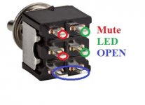
It would not be possible without introducing voltage into gain and mute circuit. You could use a micro controller but this is a simpler solution or the like. One side for mute, other for led.
Wouldn't the switch operate both legs at the same time like this? So it will not be backwards.
You show a DPDT switch but same principle. When mute is closed it is muted and LED closes (on). So when sound is off light is on - reversed of light is off sound is off.
You can use one of these: 22mm metal push button switch,latching type and momentary type,DC12V,car angel eyes switch-in Push Button Switches from Electrical Equipment & Supplies on Aliexpress.com | Alibaba Group
You push the button once, the two outer contacts are latched. Push again, the two inner contacts are connected. So when mute is on, the LED is off and vise versa. That is a good seller. I bought 3 sets of those switches and took 1.5 weeks to arrive in the US.
You push the button once, the two outer contacts are latched. Push again, the two inner contacts are connected. So when mute is on, the LED is off and vise versa. That is a good seller. I bought 3 sets of those switches and took 1.5 weeks to arrive in the US.
To me it's intuitive to have the light on when music is playing; and the light off when muted. I have done exactly this. The switch had two positions, four leads (a1, a2, b1, b2). In switch position 1, leads a1 and a2 were closed, and b1 and b2 were open. Exact opposite for switch position 2, leads a1 and a2 were open, b1 and b2 closed.
So the "a" leads went to mute: when they were closed, the amp board was muted, and the "b" leads to the LED were open (light off).
And then when the "a" leads were open, the board was un-muted, and the "b" leads were closed, light on.
I actually had two LEDs on that build, another one directly connected to indicate if the board had power or not. You can never have too many LEDs.
- Home
- Amplifiers
- Class D
- Cheap TPA3118D2 boards, modding them and everything that comes with it
