Hello all,
I've published the design files for my balanced-input chip amp under an open license (CC BY-SA 4.0). The KiCad project files and Gerbers can be found in this GitHub repository. I've also included schematics in PDF (to make them viewable without installing KiCad). Documentation is, unfortunately, non-existent at the moment. I plan to add some documentation as well as BOMs in the future. Any comments/criticisms welcome.
You can see my build using these boards here.
Attachments
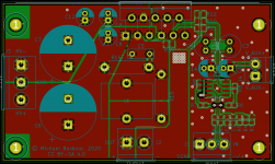

Very nice layout with attention to detail like taking the NFB via R12 from via a nettie instead of the groundplane itself.
I guess the reasoning was a) to make it symmetrical (layout wise) and b) to make the crossing over the balanced signal lines to have a potential near ground and thus less coupling into these.
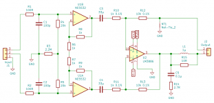
R6 will have all the bias current (200nA *2) of both amps running through it and creating noise and offset voltage (880mV).
400nA * 1kOhm = 400uV
EDIT: And anyways, if it was connected to ground it would be the exact same situation except that you introduce an unwanted ground reference at this node. IMHO everything done correctly @bmc0
EDIT: And anyways, if it was connected to ground it would be the exact same situation except that you introduce an unwanted ground reference at this node. IMHO everything done correctly @bmc0
Hmm, don't think thats correct either. Bias currents will be swallowed by the preceding output stage of the source.
It looks like you're missing some decoupling caps on the LM3886. 0.1-1 uF. Are they on the bottom? Any decoupling on the NE5532?
Tom
Tom
I don't do design..
But why R6 & R7? Why not one Rx @ 2k?
Fewer connection points and less chance at component failure / tolerance issues.
As Tfive suggested, it makes the layout more symmetrical, which theoretically reduces EM interference pickup. Also, it means one fewer component value to buy 🙂.
Tolerance isn't actually a problem at all in this position. The common-mode gain of the input buffers is unity regardless of the resistor values which means the common-mode rejection of the circuit is unaffected. I doubt that component failure is a significant concern.
[R3] will have all the bias current (200nA *2) of both amps running through it and creating noise and offset voltage (880mV).
Any noise from R3 is common-mode and therefore cancelled. The noise contribution of R3 is far below that of the other components even taking into account the finite CMRR of the difference amp stage.
It's true that a relatively large voltage is generated across R3 because of the bias current if the inputs are not connected, but this problem goes away as soon as you connect them. There's no significant thump either because the voltage is common-mode.
You can substitute a lower value for R3 if you want, but this will decrease the common-mode input impedance which means that the CMRR will be affected more strongly by source impedance mismatches between the + and - inputs.
It looks like you're missing some decoupling caps on the LM3886. 0.1-1 uF. Are they on the bottom? Any decoupling on the NE5532?
Tom
There are spots for 1206 size caps on the underside of the board for the LM3886. I used 1µF 100V X7R parts in my build, but higher capacitance would be even better in theory (as I'm sure you know).
Decoupling for the NE5532 is provided by two 22µF electrolytics. I got the idea from Bruno Putzeys who uses this decoupling scheme often. He explains his reasoning here.
Hmm, don't think thats correct either. Bias currents will be swallowed by the preceding output stage of the source.
Hmm, strictly DC-coupled really?
There will be a lot of oscillation no caps in critical positions
To operate the amp in differential mode is not recommended.
There is also only 20dB of gain for the 3886 another source of instability
A star grounding technique should be used ground-plane is not good
Last edited:
Hmm, strictly DC-coupled really?
I fail to see a problem. Even if the input has no path to ground except through R3, the voltage is common-mode and not nearly enough to exceed the common-mode input voltage range of the NE5532.
There will be a lot of oscillation no caps in critical positions
Where? My build does not oscillate.
To operate the amp in differential mode is not recommended.
According to whom?
There is also only 20dB of gain for the 3886 another source of instability
Again, my build is stable.
A star grounding technique should be used ground-plane is not good
So I guess tomchr's designs are garbage too since he uses ground planes.

Excluding the decoupling caps and the mute circuit, there are three ground connections:
1. Junction of C1 and C2. Any ground noise at this point is common-mode so it cancels.
2. At R3. Again, this is common-mode.
3. At NT1. Yet again, this is common-mode. If there's a voltage at NT1, the output of the LM3886 follows, so there is no net voltage across the load.
There are spots for 1206 size caps on the underside of the board for the LM3886. I used 1µF 100V X7R parts in my build, but higher capacitance would be even better in theory (as I'm sure you know).
Decoupling for the NE5532 is provided by two 22µF electrolytics. I got the idea from Bruno Putzeys who uses this decoupling scheme often.
Bruno is right that the ceramic cap forms a resonant circuit with the equivalent inductance of the circuit. But I suggest you reread Bruno's post. He's suggesting that you add the 22 uF electrolytic cap as a snubber, not that you replace the ceramic cap with the 22 uF electrolytic cap. That's a nice trick, actually. The ESR of the electrolytic cap tends to be on the order of a few tenths of an ohm for that capacitance, which tames any ringing caused by the ceramic cap. The low-ESR ceramic cap is needed to keep the NE5532 happy. I recall reading about that some 10 years ago in EDN or similar trade magazine.
Have you looked at the clipping performance with 4 Ω and 8 Ω load? The LM3886 can have a little parasitic oscillation when it recovers from clipping. I don't recall seeing that in a differential amp with the LM3886, but it's worth checking for. Gradually increase the input voltage (sine wave) until the amp clips and monitor the output on a scope.
BTW: If you're planning to use mounting brackets to hold the board to the heat sink, I recommend that you pull back the top copper so the bracket doesn't connect to it if it wears through the solder mask.
Tom
Last edited:
There is also only 20dB of gain for the 3886 another source of instability
The LM3886 is stable with 20 dB gain according to its data sheet. It's operating with 20 dB gain in OP's circuit. I don't see the problem.
So I guess tomchr's designs are garbage too since he uses ground planes.
Yep. All garbage. 😀
Tom
does this tomchr really uses 3886 in his design??? Also the plane is cut in smaller areas
You just shouldn't use a grnd-plane on the combination power and pre.
The output currents then run all over the plane
You just shouldn't use a grnd-plane on the combination power and pre.
The output currents then run all over the plane
Last edited:
But I suggest you reread Bruno's post. He's suggesting that you add the 22 uF electrolytic cap as a snubber, not that you replace the ceramic cap with the 22 uF electrolytic cap.
He says in the post I linked (emphasis mine):
Now, if you consider that elcaps have hardly more inductance than their own pins (contrary to popular belief), additional ceramics are unnecessary if the elcaps are small and close enough to the op amp you're trying to decouple. Their ESR and high capacitance will insure that they will never enter into any sort of resonance with other caps located elsewhere. Thus, consistently using only elcaps to decouple opamps is a no-brainer.
He's used electrolytics by themselves for decoupling both NE5532s and LM4562s in his designs. Maybe it's a bad idea, I don't know. I haven't seen any problems so far, but I lack the equipment to test it fully.
Have you looked at the clipping performance with 4 Ω and 8 Ω load? The LM3886 can have a little parasitic oscillation when it recovers from clipping. I don't recall seeing that in a differential amp with the LM3886, but it's worth checking for. Gradually increase the input voltage (sine wave) until the amp clips and monitor the output on a scope.
I don't own an oscilloscope, unfortunately, (maybe one day 🙂) but I was able to borrow one from a friend a while back to test for instability. I did not see any "buzz" when overloaded. From what I remember, the clipping behavior looked the same as in your post here.
BTW: If you're planning to use mounting brackets to hold the board to the heat sink, I recommend that you pull back the top copper so the bracket doesn't connect to it if it wears through the solder mask.
I did this for the V+1 and V-1 pours, but I figured it didn't really matter for the ground pours since the heat sinks are at ground potential too. I used these brackets in my build. I guess a non-conductive washer or something could be added between the board and bracket just in case.
So I guess tomchr's designs are garbage too since he uses ground planes.
Excluding the decoupling caps and the mute circuit, there are three ground connections:
1. Junction of C1 and C2. Any ground noise at this point is common-mode so it cancels.
2. At R3. Again, this is common-mode.
3. At NT1. Yet again, this is common-mode. If there's a voltage at NT1, the output of the LM3886 follows, so there is no net voltage across the load.
I can verify the techniques you used are all good. I used the same input frontend and an opamp that has 8 nested LME49600 buffers (in parallel) as output stage instead of the LM3886. The measurements show >-110dB THD over the whole audio frequency range (!). I used ground and power planes and even the output current flows through the whole ground plane. By taking feedback for the output amp directly from the output pin of the speakon and not from "somewhere on the groundplane" the alledged problem with using a ground plane just goes away - or probably even better - will add some shielding to the whole circuit and be beneficial. (Schematics and layout will be released soon in another thread. Don't want to pollute this one).
EDIT: And one more comment: Everything is "balanced" (or more precisely: differential) all the time. Voltages are always measured between two nodes and there is no such thing as a stable ground reference, wether using a groundplane, split planes or star ground. It just does not exist.
Last edited:
does this tomchr really uses 3886 in his design??? Also the plane is cut in smaller areas
You just shouldn't use a grnd-plane on the combination power and pre.
The output currents then run all over the plane
Don't want to sound harsh or anything, but how many amp layouts did you design, measure & optimize already? Are you repeating "common wisdom" or are these your own findings?
Sounds like a cool project, Tfive. How much output power is it capable of?
This is one of the central points in Bruno Putzeys's "The G Word" article, which is what inspired me to use the instrumentation amp topology.
Voltages are always measured between two nodes and there is no such thing as a stable ground reference, wether using a groundplane, split planes or star ground. It just does not exist.
This is one of the central points in Bruno Putzeys's "The G Word" article, which is what inspired me to use the instrumentation amp topology.
Sounds like a cool project, Tfive. How much output power is it capable of?
Depends on the speaker's impedance. With 8 Ohms you get about 15W of power. 4 ohms will be current limited at about 10W, 16 ohms voltage limited at about 10W. It's basically a headphone amp on steroids. The original design was done by opc and called LPUHP.
The thread I started a while ago is here: Comments on PCB layout for LPUHP clone wanted
I will post new schematic, layout and renderings of the v2 we just built and tested in an hour or so...
This is one of the central points in Bruno Putzeys's "The G Word" article, which is what inspired me to use the instrumentation amp topology.
Yes, me too 🙂
- Home
- Amplifiers
- Chip Amps
- Open source balanced-input LM3886 design and PCB layout