In my design? There's already a DC path through R10+R12 and R11+R13. Neither input of a standard difference amp is floating.
GotchaIn my design? There's already a DC path through R10+R12 and R11+R13. Neither input of a standard difference amp is floating.
I wonder about those NE5532 in the original schematics - how do they perform seeing 1k load? What if resistors R10, R11 were to be increased to 2k and R12, R13 increased to 20k? From the datasheet of the NE5532 it looks like it performs better seeing 2k loads?
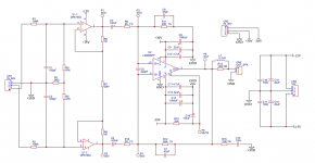
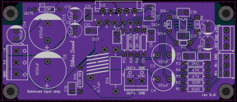
I have built the amplifier based on this schematics, but with different OPAMP and PCB board layout.
The problem is - it oscillates.
It only does so when I turn on the amp first instead of my DAC that is connected with about 3 feet mic cables. I also have speakers connected and when I turn the amplifier on I hear loud screeching sound from the speakers. However, if I turn on DAC first, and then the amp, everything is fine.
I wonder if the reason is the input bias network?
I have used all recommended stability components for the LM3886 - I don't think it is the reason for the oscillation.
I am also wondering if it is possible for OPA1652 to oscillate and pass it further to LM3886?
Any suggestions are welcome,
Thank you!
Attachments
I've never seen or heard my build of my design oscillate with the inputs floating or otherwise. Not even with a 25 ft XLR cable and long speaker cables.
So, unfortunately, I don't have any real idea at the moment. I haven't looked at your layout extremely carefully, but one thing I did notice is that R11/C6 and the negative output terminal are not tied to ground at a single point (note the net tie in my design). This could be a problem because grounding those at a single point is what ensures a high degree of ground noise immunity in a difference amp.
I can't see why this would be the case.I wonder if the reason is the input bias network?
It's possible, but that op amp shouldn't be difficult to keep happy. I've used the OPA1678 (which is essentially the same chip) in other projects and it doesn't seem to be particularly picky about supply decoupling, output loading, etc.I am also wondering if it is possible for OPA1652 to oscillate and pass it further to LM3886?
So, unfortunately, I don't have any real idea at the moment. I haven't looked at your layout extremely carefully, but one thing I did notice is that R11/C6 and the negative output terminal are not tied to ground at a single point (note the net tie in my design). This could be a problem because grounding those at a single point is what ensures a high degree of ground noise immunity in a difference amp.

Could it be the LM3886 that oscillates? My feedback resistor and capacitor paths are kind of long on the side where it connects to the output pin #3
Could be shorter, but I don't think the loop is long enough to be a considerable problem by itself. Other than what I mentioned in my previous post, nothing is jumping out as obviously problematic to me at the moment.
Perhaps @tomchr would have a good guess as to the problem with your design if he has the time to take a look. He definitely has considerably more experience in PCB design than I do.
Perhaps @tomchr would have a good guess as to the problem with your design if he has the time to take a look. He definitely has considerably more experience in PCB design than I do.
Well there you go. I totally missed that. Since the LM3886 is not unity gain stable, omitting that series resistance is sure to cause instability at high frequencies.
If you remove Cc across the inputs and Cf across the feedback resistor you'll probably find that the amp no longer oscillates.
Without Cc, Cf, and Rf2 you'll get a bit of spurious oscillation when the amp exits from clipping. That'll limit the amount of clean output power you can get. If you want the max output power add those components.
Alternatively... Did you ever measure the phase noise of this power oscillator of yours? Was it any good? Maybe you just need to change the marketing. 😀
Tom
That was a good catch! Thank you for pointing the mistake - I guess I was copying stability components from the INAMP where three NE5532 are used, and they are stable at unity gain with those capacitors... Using LM3886 as a difference amp obviously is different...
Now I am wondering if it will make sense to mirror Rf2 and Cf for the positive part of the difference amp?
Attached schematics demonstrates the question:
Now I am wondering if it will make sense to mirror Rf2 and Cf for the positive part of the difference amp?
Attached schematics demonstrates the question:
Attachments
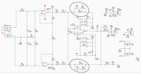
I'm pretty certain the answer is yes. The CMRR will be significantly degraded at high frequencies otherwise.I am wondering if it will make sense to mirror Rf2 and Cf for the positive part of the difference amp?
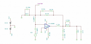
Down the rabbit hole of "stability components" Cc, Cf, Rf2:
I simulated schematics from the datasheet (also used Neurochrome website as a reference - thank you Tom!) to determine optimal values for the three. The gain was set to 10V/V. Below is the table with the results:
At the bottom of the table I have values for schematics without Cc, Cf, and Rf2. Basically shows phase margin for two gain values: 10V/V and 20V/V
Am I safe to assume that combination of Cc = 100pF, Cf = 22pF, and Rf2 = 10K is the safest to use? The negative feedback resistor Rf1 equals to 10K and set the gain to 10V/V, so at high frequencies the overall gain of the amplifier is reduced by Rf1||Rf2 = 5V/V.
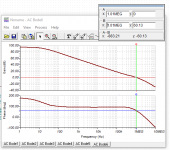
Attached are screenshots for the simulation and plot results.
I simulated schematics from the datasheet (also used Neurochrome website as a reference - thank you Tom!) to determine optimal values for the three. The gain was set to 10V/V. Below is the table with the results:
| Cc | Cf | Rf2 | Phase margin | Zero gain freq |
| 100pF | 22pF | 10k | 60.13 | 1.01MEG |
| 100pF | 27pF | 10k | 56.79 | 1.05MEG |
| 100pF | 33pF | 10k | 54.28 | 1.07MEG |
| 100pF | 47pF | 10k | 50.44 | 1.1MEG |
| 100pF | 22pF | 20k | 56.71 | 887.32k |
| 100pF | 27pF | 20k | 55.33 | 896.89k |
| 100pF | 33pF | 20k | 54.2 | 903.41k |
| 100pF | 47pF | 20k | 52.69 | 910.57k |
| 220pF | 22pF | 10k | 51.24 | 786.65k |
| 220pF | 27pF | 10k | 48.07 | 818.25k |
| 220pF | 33pF | 10k | 45.1 | 842.83k |
| 220pF | 47pF | 10k | 40.66 | 872.05k |
| 220pF | 22pF | 20k | 45.03 | 725.85k |
| 220pF | 27pF | 20k | 43.46 | 735.35k |
| 220pF | 33pF | 20k | 42.13 | 742.11k |
| 220pF | 47pF | 20k | 40.29 | 749.66k |
| Rf1 | ||||
| None | None | 20k | 84.12 | 373.94k |
| None | None | 10k | 79 | 715.58k |
At the bottom of the table I have values for schematics without Cc, Cf, and Rf2. Basically shows phase margin for two gain values: 10V/V and 20V/V
Am I safe to assume that combination of Cc = 100pF, Cf = 22pF, and Rf2 = 10K is the safest to use? The negative feedback resistor Rf1 equals to 10K and set the gain to 10V/V, so at high frequencies the overall gain of the amplifier is reduced by Rf1||Rf2 = 5V/V.
Attached are screenshots for the simulation and plot results.
Attachments
Last edited:
True that. But then again CMRR will be degraded due to the decreasing loop gain of the LM3886 anyway. I'm not sure it matters much one way or the other, but I would still add Rf2+Cf to ground on the inverting input just to keep things balanced. The components are cheap. You could simulate it and quantify the CMRR degradation with/without those components. You'll want to run the sim out to at least 1 MHz.I'm pretty certain the answer is yes. The CMRR will be significantly degraded at high frequencies otherwise.
Beware that the AC simulations with the LM3886 model are only valid well away from the supply rails. Cc is introduced to tame the behaviour when the LM3886 approaches saturation. Rf2+Cf are then added to tame the transient response after adding Cc. Anyway. My point is that Cc needs to be determined in the lab. Once you know Cc you can tune Rf2+Cf in the simulator so you get a clean transient/step response.
Tom
- Home
- Amplifiers
- Chip Amps
- Open source balanced-input LM3886 design and PCB layout