Hi,
Still continuing to have fun learning about things, I thought I'd kill two birds with one stone and learn Tina TI, whilst figuring out how to design a simple composite amp using the LM3886 as the power amp.
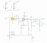
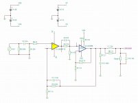
It took quite a bit of playing around with the circuit but I think I've found something that works*.
First things first I wanted to keep it as simple as possible, so no balanced inputs or DC servo (I think I'm correct in assuming that a DC servo replaces the DC coupling cap at the input).
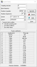
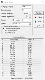
I also modelled the standard LM3886 amp with all the stability components to get a THD baseline. With a 1kHz base frequency, Tina TI's Fourier Series analysis reports a harmonic distortion of 0.054%. I know this is based on "ideal" components, and doesn't take into account parasitics and PCB layout, etc., but it's a useful baseline.
The composite version, using a LME49710 I've got the HD down to 0.0027, which is around a 20x reduction!
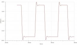
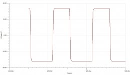
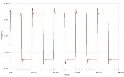
I've also tested it with 10kHz square waves with various capacitances across the load, and the square wave is stable (it took adding in C8 to achieve this, as before, any square wave would oscillate wildly; I also tried using Cf and Rf2, and while this helped with the stability, it affected the distortion to the non-composite levels).
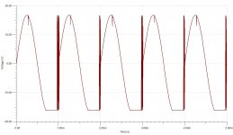
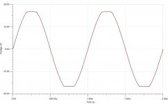
*the one area it definitely falls over is at clipping. Something catastrophic happens when the amp goes into clipping, so that will need fixing.
I guess my questions are, what additional components do I need to make this a successful design, and do I need to move anything around? I was a bit confused as to whether stability components go in the inner loop, or the outer one, or if they're needed at all.
Any and all feedback gratefully received. Thanks for your time!
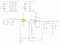
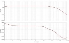
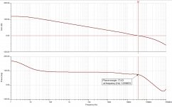
Attachments: Schematic, FFT analysis, FFT graphs (phase plot a bit weird?), Square wave @ 10nF, Square wave @ 100nF, Square wave @ 1uF, Clipping, FFT analysis of standard LM3886 circuit (all at 21x gain)
Still continuing to have fun learning about things, I thought I'd kill two birds with one stone and learn Tina TI, whilst figuring out how to design a simple composite amp using the LM3886 as the power amp.
It took quite a bit of playing around with the circuit but I think I've found something that works*.
First things first I wanted to keep it as simple as possible, so no balanced inputs or DC servo (I think I'm correct in assuming that a DC servo replaces the DC coupling cap at the input).
I also modelled the standard LM3886 amp with all the stability components to get a THD baseline. With a 1kHz base frequency, Tina TI's Fourier Series analysis reports a harmonic distortion of 0.054%. I know this is based on "ideal" components, and doesn't take into account parasitics and PCB layout, etc., but it's a useful baseline.
The composite version, using a LME49710 I've got the HD down to 0.0027, which is around a 20x reduction!
I've also tested it with 10kHz square waves with various capacitances across the load, and the square wave is stable (it took adding in C8 to achieve this, as before, any square wave would oscillate wildly; I also tried using Cf and Rf2, and while this helped with the stability, it affected the distortion to the non-composite levels).
*the one area it definitely falls over is at clipping. Something catastrophic happens when the amp goes into clipping, so that will need fixing.
I guess my questions are, what additional components do I need to make this a successful design, and do I need to move anything around? I was a bit confused as to whether stability components go in the inner loop, or the outer one, or if they're needed at all.
Any and all feedback gratefully received. Thanks for your time!
Attachments: Schematic, FFT analysis, FFT graphs (phase plot a bit weird?), Square wave @ 10nF, Square wave @ 100nF, Square wave @ 1uF, Clipping, FFT analysis of standard LM3886 circuit (all at 21x gain)
Attachments
-
 lm3886pp_tti_schematic_v01a.jpg383.6 KB · Views: 1,901
 -
 lm3886_tti_fft_thd.jpg149.3 KB · Views: 814
 -
 lm3886pp_tti_clipping_madness_v01a.jpg117.9 KB · Views: 439
 -
 lm3886pp_tti_squarewave_1u_v01a.jpg82.5 KB · Views: 381
 -
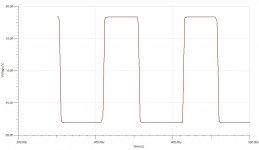 lm3886pp_tti_squarewave_100n_v01a.jpg75.5 KB · Views: 1,325
 -
 lm3886pp_tti_squarewave_10n_v01a.jpg75.9 KB · Views: 1,316
 -
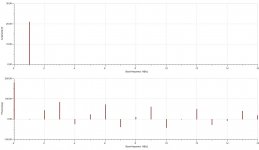 lm3886pp_tti_fft_thd_graph_v01a.jpg88 KB · Views: 1,350
 -
 lm3886pp_tti_fft_thd_v01a.jpg153.9 KB · Views: 1,802
Last edited:
I'm not aware if the outer and inner loop should have identical gain. You still need the outer loop to set the final gain, and the inner loop to be as stable as possible (so a high-ish gain). I would start with a gain of about 30dB on the inner loop.
When the LM3886 reaches clipping its internal spike protection activates, which probably drives the outer loop nuts. You can probably model in a threshold limiter or a soft-clip to help with this.
When the LM3886 reaches clipping its internal spike protection activates, which probably drives the outer loop nuts. You can probably model in a threshold limiter or a soft-clip to help with this.
Looks like you're off to a good start. Don't focus too much on the THD in the simulator as distortion is not included in the device models (at least not for the LM3886 and I don't think for the LME49710 either). Also note that anything related to the power supply and PSRR of the LM3886 is not included in the model either. In fact you can run the LM3886 model with full output swing into a 4 Ω load and its power supply current remains at a steady 50 mA. Lame, but it's what we have to work with.
As Sangram points out, you don't need the two loops to have identical gain. In fact, many of the first composite amps ran with the inner amp running open loop.
If you haven't already, I suggest reading about the LM3886 here: Taming the LM3886 Chip Amplifier – Neurochrome
I think you'll find the stability section pretty interesting. I need to update that page as I've gained new insights, but you can at least see the methodology I use to determine amplifier stability.
Once you have the amp stable in the frequency domain, run the time domain simulations. So look at overshoot with a capacitive load and clipping behaviour in the simulator.
Then once you get the amp running nicely in the simulator, build it, iron out the last kinks, and characterize the distortion in the lab.
It's a fun project. Best of luck!
Tom
Last edited:
Thanks both.
Tom, if you look at the power decoupling you may recognise the combo of capacitors I've used, so that's a clue that I've read your Taming series 😉
I did read your Stability page quite a few times, and I must admit one or two of the concepts I still find a little difficult to grasp. However a bit of background regards my experience with the 3886: I've actually designed & built my own LM3886 amp PCBs (the thread is here), which are performing well. I'm listening to a pair now, and they don't sound half bad! I don't have test gear to accurately measure distortion though, but that's another story.
Once I'd built my amps I tested them with 10kHz square waves and various capacitive loads and noticed some heavy ringing with anything above 100nF. It was experimenting with a third amp board ("Frankenstein's Monster") that I discovered that (at least with my layout, etc.) the Thiele network specified in the data sheet (0.7uH || 10ohm) wasn't adequate, and a larger inductor (I estimate about 1.5uH) and a much smaller resistor (1.5ohm) sorted things out.
The sim circuit has the Zobel and Thiele networks for stability, and the Theile components are those I arrived at with my practical experiments. This is keeping the capacitive oscillations under control in the sim.
In a "Bare" LM3886 circuit, the 220p cap between IN+ and IN- keeps the clipping behaviour under control, but including that in my sim sends the amp into crazy oscillations that would undoubtedly blow up my speakers!
Now I've got the hang of Tina TI (better than LT Spice for a number of reasons) I'll have to try some of the sims you detail in your article. I think I need to get my head around the inner and outer loops, and what each contributes to the circuit.
I've since changed the inner loop gain, and found that a smaller gain seems to work better than a larger gain. I'll also try open loop to see how that works.
Thanks, Christian
You must understand that by making composite, you surly reduce the distortion numbers but you don't make it sound better. To show yourself and others, you succeeded in reducing the numbers, you must be equipped with expensive distortion measuring means.
@zarandok LM3886 & LME49720 composite amp could measure down to 0.0008% but he couldn't make it sound as good as his old Toshiba amplifier.
For your knowledge, the LM3886 is perfectly stable with a gain of 2.8 with 180/100 ohm feedback resistors, it delivers its best sound.
@zarandok LM3886 & LME49720 composite amp could measure down to 0.0008% but he couldn't make it sound as good as his old Toshiba amplifier.
For your knowledge, the LM3886 is perfectly stable with a gain of 2.8 with 180/100 ohm feedback resistors, it delivers its best sound.
....assuming that a DC servo replaces the DC coupling cap at the input...
No.
Tom, if you look at the power decoupling you may recognise the combo of capacitors I've used
PS decoupling of ideal voltage sources?
Make sure you draw it close to the pins 🙂
You must understand that by making composite, you surly reduce the distortion numbers but you don't make it sound better. To show yourself and others, you succeeded in reducing the numbers, you must be equipped with expensive distortion measuring means.
@zarandok LM3886 & LME49720 composite amp could measure down to 0.0008% but he couldn't make it sound as good as his old Toshiba amplifier.
For your knowledge, the LM3886 is perfectly stable with a gain of 2.8 with 180/100 ohm feedback resistors, it delivers its best sound.
Hello kokoriantz
"Gain of 2.8 with 180/100 ohm feedback resistors"
Did you actually use 180/100 ohm negative feedback resistors in the composite amplifier? Is the 3886 with such a low gain stable in the composite amplifier?🙂
I have several versions all working with 180ohm 1w 100ohm ½w. The best LM3886 circuit I have runs with floating single supply 52V driven with 600:10k input transformer.
You can see the stability also on the simulator, it needs a few pF parallel 180 ohm for perfect square wave, but it doesn't make any difference on the sound.
I couldn't make the LM3886 sound better in composite, except "My_Fef"2
Which reproduces pure female voices, but bad presence.
And tube composite with a gain of 3.
ANDREA a Democratic hybrid amp for luxury sound
Last edited:
I have several versions all working with 180ohm 1w 100ohm ½w. The best LM3886 circuit I have runs with floating single supply 52V driven with 600:10k input transformer.
You can see the stability also on the simulator, it needs a few pF parallel 180 ohm for perfect square wave, but it doesn't make any difference on the sound.
I couldn't make the LM3886 sound better in composite, except "My_Fef"2
Which reproduces pure female voices, but bad presence.
And tube composite with a gain of 3.
ANDREA a Democratic hybrid amp for luxury sound
Interesting experience
thank you for your sharing🙂
PS decoupling of ideal voltage sources?
Make sure you draw it close to the pins 🙂
OK, OK, I'll take it. It's tough being the "noob" on a place like this. As I said, I'm still learning, so a bit of **** taking is to be expected. 🙂
Anyway, more research and blatant theft later, and I seem to have arrived at a circuit that appears stable under simulation, and handles the clipping behaviour. I added the resistor divider from jeanleflambeur's composite amp, just to see what it did, and lo and behold, no more horrific oscillations upon clipping. It took me a while to see how it was working but I noticed it was clipping the LME49710 before the LM3886. The resistor values aren't the same because my feedback resistor values are a bit different, so they needed to be tuned to something more appropriate. I also played around with the small capacitors to achieve the results I ended up with. So thank you Jean!
I might not yet build this one, but it's been fun learning. Thanks for the comments.
Here are some images.
In order: updated schematic (sans decoupling caps 😉 ), closed loop Bode plot, clipping behaviour, 10kHz square wave with 100nF, 10kHz square wave with 470nF, open loop schematic, open loop plot showing phase margin.
Attachments
-
 lm3886pp_tti_ol_schematic_v01c.jpg409.4 KB · Views: 381
 -
 lm3886pp_tti_squarewave_470n_v01c.jpg76.6 KB · Views: 580
 -
 lm3886pp_tti_squarewave_100n_v01c.jpg197.9 KB · Views: 492
 -
 lm3886pp_tti_clipping_v01c.jpg180.9 KB · Views: 496
 -
 lm3886pp_tti_cl_bode_v01c.jpg194.9 KB · Views: 586
 -
 lm3886pp_tti_schematic_v01c.jpg475.2 KB · Views: 621
 -
 lm3886pp_tti_ol_bode_v01c.jpg502.2 KB · Views: 399
I've built and tested a LM3886 composite amp having almost the same circuit. IIRC with similar values you have shown it oscillates even though it looks fine in Spice. You need to add a compensation cap to LME49710. Also you should reserve space for a cap between LM3886 inputs. It is probably needed if you wish to have clean clipping. Then when testing you can see which compensations work best.
/Martti
/Martti
Hi, are you talking about a small value (pF) cap between the output and non-inverting input of the LME49710? I see that on jeanleflambeur's schematic. I'll add one into the sim and see what it does! Thanks.You need to add a compensation cap to LME49710.
You must understand that by making composite, you surly reduce the distortion numbers but you don't make it sound better.
In my experience, as well as that of my customers, the composite amp beats the non-composite on sound quality as well. Maybe you should try a good composite design... 🙂
Tom
Nuno Silva a musician and audiophile DIY has replaced his composite LM3886 "Modululs86" definitely by Mosfet discreet amplifier AP11 turbo in kit. He has several recordings of the sound of both amplifiers in the same room with the same speakers. You can hear how the composite amplifier is so uncomfortable to listen to.You must understand that by making composite, you surly reduce the distortion numbers but you don't make it sound better. To show yourself and others, you succeeded in reducing the numbers, you must be equipped with expensive distortion measuring means.
@zarandok LM3886 & LME49720 composite amp could measure down to 0.0008% but he couldn't make it sound as good as his old Toshiba amplifier.
For your knowledge, the LM3886 is perfectly stable with a gain of 2.8 with 180/100 ohm feedback resistors, it delivers its best sound.
Amplificador AP11 Turbo do Arnaldo Piacente - YouTube
https://www.youtube.com/results?search_query=modulus+86
Last edited:
Right. Because clearly you can judge sound quality from a YouTube video. In particular when you're comparing the AP11 playing a simple vocal track against the Modulus-86 playing an electronica track. 🙂
Oh, well. You believe what you believe. Thanks for the laugh.
Tom
Oh, well. You believe what you believe. Thanks for the laugh.
Tom
Last edited:
Nuno Silva a musician and audiophile DIY has replaced his composite LM3886 "Modululs86" definitely by Mosfet discreet amplifier AP11 turbo in kit. He has several recordings of the sound of both amplifiers in the same room with the same speakers. You can hear how the composite amplifier is so uncomfortable to listen to.
Amplificador AP11 Turbo do Arnaldo Piacente - YouTube
https://www.youtube.com/results?search_query=modulus+86
Let us for the moment ignore the ludicrousness of judging SQ via a YouTube video. But I cannot find information on the AP11 Turbo amplifier or a discussion of it. Link please? Thank you in advance.
Your customer threw away your product and that makes you laugh.
No. Your argument and "evidence" provided to support it made me laugh.
If you expect an amp to add to the sonic signature of the source material, a well-designed composite amp will disappoint you. A tube amp or maybe one of Pass's JFET buffers would be more likely to suit your taste.
I have no delusion of making everybody happy all the time. But I do cringe when I see statements such as "all composite amps sound bad" as you indicated in Post #5.
Either way, I commend 'vfxsoup' for taking on the challenge of designing a composite amp with the LM3886. It's a fun engineering challenge.
Tom
- Home
- Amplifiers
- Chip Amps
- LM3886++ Simplest Composite Amp