I admire your circuit and believe it has all the appropriate adjustment "handles." I also like omission of C22--- it's always bothered me.
During test, I'd remove the C8 restriction on test frequency. My only advice re caps is to set C4=0 and let C2 control rolloff of U2. As a tweaking strategy, I'd iteratively reduce values of C2 and C3 until each is contributing about 1 dB of response peaking, with the goal of maximizing bandwidth. Be careful re test amplitudes at high frequencies to avoid damaging R9.
Only other thoughts are musings about clipping behavior. I believe the lead-lag network (C3, R5, R12) has great adjustment flexibility. I observe that its low frequency attenuation could be set so that onset of clipping would be determined by U2 so that U1 never can be driven into overload. I suspect this might produce the least "complicated" sticking behavior in clipping but that does leave a bit of output power sacrificed. Just a thought.
Cheers!
I'd leave it in. If you don't find it useful, just don't populate it.I admire your circuit and believe it has all the appropriate adjustment "handles." I also like omission of C22--- it's always bothered me.
Tom
Pretty good thought. I've had the same thought. You can certainly make that work for a single supply voltage, so if you're using a regulated ±30 V supply, you're golden. If you intend the circuit to operate well on an unregulated supply, you'll have to leave a lot of available output power on the table if you want the circuit to work at low mains voltage.Only other thoughts are musings about clipping behavior. I believe the lead-lag network (C3, R5, R12) has great adjustment flexibility. I observe that its low frequency attenuation could be set so that onset of clipping would be determined by U2 so that U1 never can be driven into overload. I suspect this might produce the least "complicated" sticking behavior in clipping but that does leave a bit of output power sacrificed. Just a thought.
Another option would be to make the clipping levels dependent on the power supply. That's what Bob Cordell does in his Klever Klipper. Unfortunately, even when it's adjusted to its optimal clipping point, it degrades THD pretty early. I took a close look at the Klever Klipper here: https://neurochrome.com/pages/super-gainclone-with-klever-klipper
Tom
Attachments
Pretty good thought. I've had the same thought. You can certainly make that work for a single supply voltage, so if you're using a regulated ±30 V supply, you're golden. If you intend the circuit to operate well on an unregulated supply, you'll have to leave a lot of available output power on the table if you want the circuit to work at low mains voltage.
Another option would be to make the clipping levels dependent on the power supply. That's what Bob Cordell does in his Klever Klipper. Unfortunately, even when it's adjusted to its optimal clipping point, it degrades THD pretty early. I took a close look at the Klever Klipper here: https://neurochrome.com/pages/super-gainclone-with-klever-klipper
Tom
Thanks Tom and Mark,
I've got Cordell's 2nd edition book--- maybe I should get the Self book, too!
I've long pondered how to maintain low distortion till onset of clipping. My best musings have a topology similar to the diagram in post #39. As discussed, I'd adjust gains so that clipping onset is determined by U2. I'd add anti-parallel RF Schottky diodes across U2's differential input to clamp C2's excursion into the weeds while U2 is in overload. And as Tom suggests, I'd devise tracking supplies for U2 derived from U1 supply rails to eek out best compromise power output from the local utility.
Steve
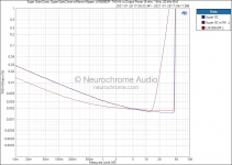
Great find, Mark. Thanks. I would have liked to see THD+N vs output voltage as well. That would hammer home the point of "no added distortion until clipping" better than the THD+N vs frequency. Sounds like I have a project for a snow day.People who own the second edition of Douglas Self's book "Small Signal Audio Design", might want to check out his feedforward clipper idea on pages 701-702. No added distortion all the way up to the very onset of clipping (!).
I'd certainly recommend Self's Small Signal book. My copy (2nd ed) was open on page 330/331 when Mark's comment trickled in. 🙂I've got Cordell's 2nd edition book--- maybe I should get the Self book, too!
I'd recommend Self's power amp book as well. The newer editions do contain added material, but the central points are still those from his article series in Wireless World from the mid 1990s. So if you have the articles, I wouldn't rush out and buy the book. But the book is certainly a convenient way of collecting the material. 🙂
I think you may have U1 and U2 reversed (or maybe we're looking at different schematics), but I think we are thinking along the same lines. The reference for the clipper should be derived from the power supply to the LM3886. I think you can do that in Self's circuit by changing some resistor ratios (and connections). Then all you'd have to deal with is resistor tolerances and part-to-part variation in Vod on the LM3886. The output dropout voltage (Vod) is a specified parameter, so that seems like a manageable task. And, of course, if you don't plan for mass production you can just make it adjustable.And as Tom suggests, I'd devise tracking supplies for U2 derived from U1 supply rails to eek out best compromise power output from the local utility.
My only concern with clipping references derived from the supply rails is that they potentially reduce the PSRR. I'd definitely look at that in simulation to ensure that the clipper doesn't degrade the performance in the audio band below clipping.
Tom

- Home
- Amplifiers
- Chip Amps
- LM3886++ Simplest Composite Amp