10kHz square wave with 100nF, 10kHz square wave with 470nF, open loop schematic, open loop plot showing phase margin.
I would go beyond 1 uF in simulation. If the amp behaves well with a few uF on its output, there's hope it'll behave in reality as well.
Be careful with small capacitors. 2.2 pF is getting to the point where the stability of the amp will change when your cat walks by. 🙂
I've built and tested a LM3886 composite amp having almost the same circuit. IIRC with similar values you have shown it oscillates even though it looks fine in Spice. You need to add a compensation cap to LME49710. Also you should reserve space for a cap between LM3886 inputs.
That's been my experience as well. The cap across the inputs of the LM3886 can wreck stability in some cases. I support leaving a spot open for it, though. I would also look at the compensation schemes used in the MyRef (and others) to see if you can come up with something that gives you more loop gain at 20 kHz.
Tom
In fact, many of the first composite amps ran with the inner amp running open loop.
Could you explain why the composite amps then started having closed loop inner amps? After all, with local feedback we only exchange gain and bandwidth, isn't it? That is, G*H becomes G/(1+G*H) and phase shift of the inner amp only seems to increase after local feedback. Are there any specific advantages to having local feedback, particular to audio, that are being preferred here? Thanks.
Last edited:
Right. Because clearly you can judge sound quality from a YouTube video. In particular when you're comparing the AP11 playing a simple vocal track against the Modulus-86 playing an electronica track. 🙂
Oh, well. You believe what you believe. Thanks for the laugh.
Tom

Hello members,
Like many here, I have also managed to come up with a composite LME49710 / LM3886 spice simulation of my own (attached). However, I do not know if it could be termed as 'simple'.
The models I'm using in the simulation are op-amp "macromodels", as I have an old version of PSPICE that is not compatible with the detailed sub-circuits found these days. However, the loop-gain and pole placement in all the models exactly correspond to the curves from the respective datasheets. Please also note that a "real" amplifier along these lines would have to be compensated for a bandwidth lower than in the simulation.
Please note that my compensation scheme maybe slightly different from the methods usually seen in this forum. More details and results of the simulation are attached. All results including gain and phase margins are for 8 ohms shunted by a 100nF capacitor.
Thank you.
Attachments
That's been my experience as well. The cap across the inputs of the LM3886 can wreck stability in some cases. I support leaving a spot open for it, though. I would also look at the compensation schemes used in the MyRef (and others) to see if you can come up with something that gives you more loop gain at 20 kHz.
Tom
The cap across the inputs of lm3886 never worked for me. That lowered margin for stability.
Sophisticated design!Hello members,
Like many here, I have also managed to come up with a composite LME49710 / LM3886 spice simulation of my own (attached). However, I do not know if it could be termed as 'simple'.
The models I'm using in the simulation are op-amp "macromodels", as I have an old version of PSPICE that is not compatible with the detailed sub-circuits found these days. However, the loop-gain and pole placement in all the models exactly correspond to the curves from the respective datasheets. Please also note that a "real" amplifier along these lines would have to be compensated for a bandwidth lower than in the simulation.
Please note that my compensation scheme maybe slightly different from the methods usually seen in this forum. More details and results of the simulation are attached. All results including gain and phase margins are for 8 ohms shunted by a 100nF capacitor.
Thank you.
Friends, have you actually produced and verified it?
I tried to make a traditional 3886 composite amplifier. In practice, I found that it is necessary to leave more margin on the phase margin obtained by TINA simulation in order to maintain stability in actual manufacturing.
The phase of the simulation needs to reach 105°-110°, but your design is roughly 117°? You may encounter some stability issues.
Another problem, 3886 is not very friendly to composite amplifiers. It is easy to oscillate when clipping and overloading. Even without considering the composite amplifier, the 3886 itself is easy to oscillate when overloaded (when there is no lead-lag compensation, such as the application state of the composite amplifier).
In my opinion, the 3886 without lead and lag compensation is extremely sensitive. Any event that may cause clipping (even a momentary accident) may cause oscillations.
So how to ensure that 3886 will not be overloaded before 49720 under any circumstances is a very important matter.
The cap across the inputs of lm3886 never worked for me. That lowered margin for stability.
In the composite amplifier, 3886 needs to provide a larger bandwidth than 49720 in order to stabilize the circuit.
The use of hysteresis compensation capacitors at the input of the 3886 will greatly attenuate the available bandwidth of the 3886. This seems to go against the principle of composite amplifiers. I don’t know how to understand...
Yes, I agree with that the feedback path (3886) needs to be faster than the forward path (497XX) and this is usually achieved by sacrificing the HF gain from the forward path (by integrating) to make the other amp appear faster. However, one could pick a lower bandwidth device (say OPA134) for the outer amplifier and use less compensation (I guess), will try that.
We want lots of loop-gain from DC to 20kHz, but still a first order slope at the gain crossing which are, unfortunately, two contradicting things.
We want lots of loop-gain from DC to 20kHz, but still a first order slope at the gain crossing which are, unfortunately, two contradicting things.
Could you explain why the composite amps then started having closed loop inner amps? After all, with local feedback we only exchange gain and bandwidth, isn't it?
We also push any phase wobble below unity gain, which can help with stability. The behaviour at clipping can be more predictable with the inner loop closed.
The cap across the inputs of lm3886 never worked for me. That lowered margin for stability.
Yep, but it cleans up the clipping behaviour, so you now have cleaner clipping but a bigger stability challenge. Tradeoffs, tradeoffs.
The Rf2 + Cf in the regular LM3886 circuit is the frequency compensation added to compensate for Cc across the inputs.
Like many here, I have also managed to come up with a composite LME49710 / LM3886 spice simulation of my own (attached). However, I do not know if it could be termed as 'simple'.
It's really pretty good in terms of simplicity. Note that your 1 pF compensation cap is awfully small. That basically means you change the amp performance if you wave your hand near it. You'll probably want at least 10 pF (and change the other impedances accordingly).
Tom
zergxia said:The phase of the simulation needs to reach 105°-110°
tomchr said:We also push any phase wobble below unity gain, which can help with stability. The behaviour at clipping can be more predictable with the inner loop closed.
Note that your 1 pF compensation cap is awfully small .... You'll probably want at least 10 pF...
Yes, Sir, and yes Sir. Please see a slightly better version (attached), non-inverting and probably the simplest (potentially working) circuit I can imagine. Loop gain at DC and 20k are 138dB and 51dB respectively. Load, output capacitance etc. same as before. Thank you !
Attachments
Hello all,
I happened to notice (while reading on the internet) that the TINA model for LM3866 uses a very different value for the gain-bandwidth product when compared to that in the datasheet, and therefore decided to give TINA-TI a try. The following are a few observations I was able to make in the past one or two days of TINA usage.
* Making interconnections between components is painful but changing component values is easier.
* PSPICE has more generic parts (gain block, LaPlace block, limiters etc.), which I found missing (maybe TI added to later versions).
* TINA's GUI moves the Refdes and part value together, which is great.
* No improvements in simulation speed but TINA surely doesn't open a hundred windows like PSPICE does.
* Post-processing is better, with the ability to define new functions from existing output (like O/L gain from C/L circuits).
* Adding a new TI macromodel is very easy, but adding a generic PSPICE model (LIB) is equally complicated as in PSPICE.
* More accurate models than PSPICE, at least for National / TI products (very important advantage in audio circuit design).
* TINA identifies (and allows selection) from the multiple subcircuits within a model, whereas PSPICE uses the first subcircuit by default.
* It's easier to simultaneously view transient and AC response than in PSPICE (possible only new output markers).
* TINA did not respond to new output markers or changes in existing ones (have to simulate again). PSPICE fully supports on-the fly changes to any of its markers, a very important advantage indeed.
* No FFT (unlike SPICE), only fourier series (i.e. periodic waveforms only), and the THD may also not translate well into real-life situations.
* TINA does not show data point resolution like PSPICE and the cursors are also a pain to move using the keyboard.
* TINA's ERC is more forgiving than PSPICE's e.g. unconnected components generate warnings, not errors.
* The show/hide curves in TINA is easier to handle than the delete/undelete function in PSPICE.
* Annotation of points is easier in TINA than in PSPICE.
* TINA (v9.2.30.221) never crashed even with a heavy OS (Windows Vista SP2) on a modest computer (Core2Duo T8100). Though PSPICE is trustworthy and not proprietary like LTSpice/TINA, it has died on me several times in the past.
On the whole, having used PSPICE for over 15 years, I faced very few problems getting results out of TINA. In fact I was able to draw and simulate something in less than 10 minutes! However, personally, I think I like PSPICE better. Meanwhile, I also happened to come up with a much better LM3886 composite amplifier in TINA (using the TINA models from TI) whose results (for 8 ohms load shunted by 1uF capacitor) are attached.
Thanks.
Attachments

Divider and 3866 input-side values scaled for inverting operation, gain, phase feed-forward capacitor adjustments and step responses.


Note that THD is not included in the LM3886 model, so your THD sims will be off. I still find the THD sim useful as a fundamental "is it broken" test, though.
Tom
Tom
Note that THD is not included in the LM3886 model, so your THD sims will be off. I still find the THD sim useful as a fundamental "is it broken" test, though.
Hi Tom,
The THD was just for fun (as you may have already guessed) and I didn't expect it to be modelled at all, but thanks anyway for confirming. I usually read a little into the models I use (a good habit) and both TI-models for 3886 clearly state the following:
"Notes: The following parameters are being modeled: Open Loop Gain, Closed Loop Gain, GBWP, Slew Rate, Offset Voltage, Ibias, Quisent current, Output Swing, Short Circuit Current, PSRR+ ,CMRR, Icc trans current and Mute current."
I hope the above information would be helpful to anyone who assumes device models to be perfect. And by the way, my "is it broken" test is the FFT (picture) that instantly tells me when something is wrong. Besides indicating DC offsets, ripple, oscillations etc., it is capable of transforming non-periodic signals as well.
Regards.

Last edited:
Finally, people who think that the 3886 "must" have only its minimum gain of 10 may simply shift some loop gain from the 3886 to the error amplifier section as shown in the picture below. The feed-forward capacitor has also been adjusted for optimum step response. Thank you!


..I think I've found something that works*...
Dear Vfxsoup,
Here are results of "few" modifications to your circuit from post #1, and believe me, it does not fail during clipping. I think you were in the right direction right from the beginning, and I'm sure you're brilliant enough to get there.
All the best.

Hello,
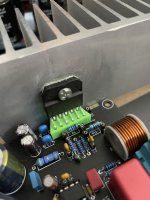
It's been a while since I've been here. Lots of things happened over the past year-or-so, which got in the way of my audio hobby. But I've returned and have built a version of this amp. After a horrible false start (In my haste I put the op-amp in backwards and things got hot and popped), and some bug fixing to get the thing stable, I have a working composite amp. It displays perfect clipping behaviour, plays nice with reasonably high capacitances on the output with square waves, and sounds fine from my testing.
However a quick FFT using my scope (Siglent SDS-1104X-E) showed some relatively large harmonics, and a rough calculation gave a THD of around 0.2%, when it should be a few orders of magnitude smaller. I suppose it could be any number of things, including my DIY 8ohm load, the signal generator, or that many of the components are socketed, including the LM3886.
On that last point, the 3886 is a bugger to desolder, especially from plated thru-hole boards, and as I only had one good chip going spare I didn't want to commit it to this dev board, so I 3D printed a socket, which uses the little fork receptacles from headers. Works really quite nicely but I'm aware that the additional length to the legs might not be ideal for measurements.
(The photo also shows a bobbin for the inductor I printed).
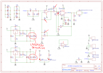
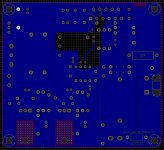
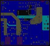
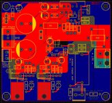
Attached are the schematic of the build as it stands, and the PCB layout. It's a 4 layer board, as they were as cheap to get made as 2 layers at that size, and it helped with the routing. I left the spot for the cap between the inputs, but haven't used it as the clipping is perfect without it. I also have spots for SMD decoupling caps on the LM3886 power pins.
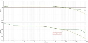
I'd love some feedback on the layout, and component choices, in particular the capacitor values used around the feedback loops; I tweaked these based on simulation (plot attached) to get the phase margin to between -105 and -110 degrees, as someone stated earlier in the thread. I've yet to run the bode plot using my scope, since I don't have a Siglent function generator so will need to do some cool computer hackery to sync it up with my Feeltech generator.
Thanks!
It's been a while since I've been here. Lots of things happened over the past year-or-so, which got in the way of my audio hobby. But I've returned and have built a version of this amp. After a horrible false start (In my haste I put the op-amp in backwards and things got hot and popped), and some bug fixing to get the thing stable, I have a working composite amp. It displays perfect clipping behaviour, plays nice with reasonably high capacitances on the output with square waves, and sounds fine from my testing.
However a quick FFT using my scope (Siglent SDS-1104X-E) showed some relatively large harmonics, and a rough calculation gave a THD of around 0.2%, when it should be a few orders of magnitude smaller. I suppose it could be any number of things, including my DIY 8ohm load, the signal generator, or that many of the components are socketed, including the LM3886.
On that last point, the 3886 is a bugger to desolder, especially from plated thru-hole boards, and as I only had one good chip going spare I didn't want to commit it to this dev board, so I 3D printed a socket, which uses the little fork receptacles from headers. Works really quite nicely but I'm aware that the additional length to the legs might not be ideal for measurements.
(The photo also shows a bobbin for the inductor I printed).
Attached are the schematic of the build as it stands, and the PCB layout. It's a 4 layer board, as they were as cheap to get made as 2 layers at that size, and it helped with the routing. I left the spot for the cap between the inputs, but haven't used it as the clipping is perfect without it. I also have spots for SMD decoupling caps on the LM3886 power pins.
I'd love some feedback on the layout, and component choices, in particular the capacitor values used around the feedback loops; I tweaked these based on simulation (plot attached) to get the phase margin to between -105 and -110 degrees, as someone stated earlier in the thread. I've yet to run the bode plot using my scope, since I don't have a Siglent function generator so will need to do some cool computer hackery to sync it up with my Feeltech generator.
Thanks!
Attachments
Can’t comment on capacitors size. Just follow what simulation tells. But the schematics composite part looks very good for me 👍Hello,
It's been a while since I've been here. Lots of things happened over the past year-or-so, which got in the way of my audio hobby. But I've returned and have built a version of this amp. After a horrible false start (In my haste I put the op-amp in backwards and things got hot and popped), and some bug fixing to get the thing stable, I have a working composite amp. It displays perfect clipping behaviour, plays nice with reasonably high capacitances on the output with square waves, and sounds fine from my testing.
However a quick FFT using my scope (Siglent SDS-1104X-E) showed some relatively large harmonics, and a rough calculation gave a THD of around 0.2%, when it should be a few orders of magnitude smaller. I suppose it could be any number of things, including my DIY 8ohm load, the signal generator, or that many of the components are socketed, including the LM3886.
On that last point, the 3886 is a bugger to desolder, especially from plated thru-hole boards, and as I only had one good chip going spare I didn't want to commit it to this dev board, so I 3D printed a socket, which uses the little fork receptacles from headers. Works really quite nicely but I'm aware that the additional length to the legs might not be ideal for measurements.
(The photo also shows a bobbin for the inductor I printed).
Attached are the schematic of the build as it stands, and the PCB layout. It's a 4 layer board, as they were as cheap to get made as 2 layers at that size, and it helped with the routing. I left the spot for the cap between the inputs, but haven't used it as the clipping is perfect without it. I also have spots for SMD decoupling caps on the LM3886 power pins.
I'd love some feedback on the layout, and component choices, in particular the capacitor values used around the feedback loops; I tweaked these based on simulation (plot attached) to get the phase margin to between -105 and -110 degrees, as someone stated earlier in the thread. I've yet to run the bode plot using my scope, since I don't have a Siglent function generator so will need to do some cool computer hackery to sync it up with my Feeltech generator.
Thanks!

- Home
- Amplifiers
- Chip Amps
- LM3886++ Simplest Composite Amp