Changed the gain to 16db (6k65 / 1k21 feedback R's), and cleaned up a couple small power-supply-related things. It didn't expect it would make a significant difference in the distortion spectra, and it didn't.
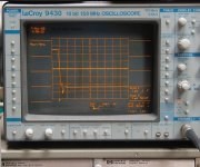
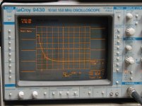
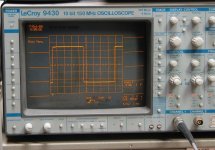
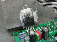
Had a convo on another forum about the "wrinkles" in the LM1875 open-loop gain/phase plot, and decided to look at the 1kHz square wave response. Rising edge is fairly well behaved; falling edge is not. See 1st photo attached. Settling from the falling edge induces two resonances above 1MHz. So I added capacitance across the 6k65 feedback R to compensate. 56pf (425kHz) reduced the overshoot, but left both resonances clearly visible. 100pF (240kHz) cleaned them up better (2nd pic). 3rd pic shows the resulting well-behaved 1kHz sq wave.
Set it up to listen, and for the first time I heard what I could honestly call an enjoyable musical presentation coming from this amp. The edgyness had been significantly reduced! No perfect by any means, but significantly better.
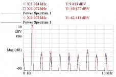
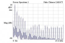
Took it back to the bench and measured the distortion spectra. 3rd harmonic distortion had been lowered by over 12dB just from adding the feedback capacitor! The 4th pic shows the before/after of adding the cap. I don't think I have ever seen anything as dramatic as this. Or as clear a demonstration of the a-musicality of 3rd harmonic distortion.
Unfortunately I think this is about as good as it gets in this configuration; I can't thnk of anything else to do. As it is, these headphones still deserve a better amp than this. Maybe piggybacking a little pcb with an input buffer and exploring inverted mode. Am open to ideas if you have any.
Had a convo on another forum about the "wrinkles" in the LM1875 open-loop gain/phase plot, and decided to look at the 1kHz square wave response. Rising edge is fairly well behaved; falling edge is not. See 1st photo attached. Settling from the falling edge induces two resonances above 1MHz. So I added capacitance across the 6k65 feedback R to compensate. 56pf (425kHz) reduced the overshoot, but left both resonances clearly visible. 100pF (240kHz) cleaned them up better (2nd pic). 3rd pic shows the resulting well-behaved 1kHz sq wave.
Set it up to listen, and for the first time I heard what I could honestly call an enjoyable musical presentation coming from this amp. The edgyness had been significantly reduced! No perfect by any means, but significantly better.
Took it back to the bench and measured the distortion spectra. 3rd harmonic distortion had been lowered by over 12dB just from adding the feedback capacitor! The 4th pic shows the before/after of adding the cap. I don't think I have ever seen anything as dramatic as this. Or as clear a demonstration of the a-musicality of 3rd harmonic distortion.
Unfortunately I think this is about as good as it gets in this configuration; I can't thnk of anything else to do. As it is, these headphones still deserve a better amp than this. Maybe piggybacking a little pcb with an input buffer and exploring inverted mode. Am open to ideas if you have any.
Attachments
G'day Mate,
Just my 2 cents but the LM1875 is generally considered to be unstable below a gain of 10x.
Av = ( R1 + R2 ) / R2
(6.65+1.21)/1.21 = 6.45x gain.
I suspect if you change to something like 10-12k and 1k for the feedback resistors you might get better results.
This is the standard implementation that is something like a benchmark for LM1875 amps.
Hi
i agree with Sadface.
BTW...are you using LM185 from serious verndor?...
in this thread we try a lot:
eBay mono LM1875 kit
with the result = forget the delivered parts, use original parts from mouser, digikey etc.
to push LM1875 (TDA2050UTC) to the limit for better SQ(power) you have to create a composite amp:
LM1875 in parallel configuration and used in a composite amplifier.
chris
Sadface,
That is why I first tested it at 10x (9k / 1k), and got the same results. See distortion spectra in post #19. For this, 6.65 / 1.21 + 1 = 6.5 = 16dB.
Look at this interesting little power amp, which runs it at 4X (with 2x input divider):
$35.69 JUNTEK DPA-1698 Dual-channel DDS Function Signal Generator Power Amplifier - 0-100KHz signal bandwidth / US at FastTech - Free Shipping
chermann, these LM1875T's are from Digikey. This not a kit build, it came as a bare pcb. All of the other parts I had on hand, none of them are junk.
I've read through some of that parallel/composite thread, there are some interesting ideas but their goals are different (more power), and noone was measuring distortion. A guy on youtube measured it, but with the FFT on an 8-bit scope! Looked very clean, of course! Maybe he doesn't know how useless that is...
In fact, the only other distortion spectra measurement of chip amps I can find is from this 1993 article:
Spectrally Challenged - distortion spectra of audio power chips
and it shows pretty much what I am measuring. A very stinky spectra. They all look bad.
The 1875 can take +/- 30 volts, the data sheet spec is at +/- 25 volts
Also gain at less than 10 is not recommended.
So put a giant heat sink, the idle current is 100 mA, so it is needed.
Set the volume at about 75%, using the input to control final volume.
I listen to music from my computer, the sound output feeds an amplifier.
I use the Winamp program to control volume, the amplifier volume knob is at about 2 o'clock, less than that causes sound to lose its bass and treble, it sounds dull.
The set is a Philips AW 666, most likely Matsushita (Panasonic) 7161 chips driven from 0-18 windings in the mains transformer.
I have not checked this set properly, I got it for 150 Rupees in the flea market here, or about 2 dollars...The chip and voltage details may not be exact.
First check your capacitor voltage ratings before doing this, and earthing also.
Let us know what happens.
Last edited:
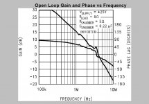
BTW, here is the 1875 (as an inverter) open-loop gain and phase vs freq. plot. At gain of 10X it has about 45º of phase margin. That's probably why they spec it as minimum gain. It's still about 40º at 6.5X.
Also BTW, I posted the link to the Juntek amplifier because it uses LM1875's at 4X gain... and users report no stability issues with it.
NareshBrd, I don't need higher voltage or giant heatsink, these headphones are a very easy load to drive (12 to 18 Ohms, depending on how the xfmrs are comensated). A 2"x3" finned heatsink on each chip is only warm to touch at even the loudest levels I'll use.
Attachments
Last edited:
Just see what happens at a higher voltage, with regard to distortion.
And this is really high powered for a headphone.
Try it on a speaker with 4-8 ohms, about 3 to 4 inches in size also, because the 1875 is a well regarded chip, your problem sounds much too bad for its reputation.
And this is really high powered for a headphone.
Try it on a speaker with 4-8 ohms, about 3 to 4 inches in size also, because the 1875 is a well regarded chip, your problem sounds much too bad for its reputation.
I already did. No difference. Try it. Nothing magical happens with a higher ps voltage, except heat disspation goes up. Look at p.4 of the "Spectrally Challenged" link in post #24. The LM1875 harmonic distortion spectra is awful, the same as what I measure. Even in the mid-1990's, several chip amps were better.
These are transformer-coupled electrostatic (electret) headphones.
Most "reputations" are totally subjective. The measurements are acurate, and correctly depict the sound quality.
Here's another way of looking at this situation.
The output of the DAC at full-code is 2.18V RMS. Using a 10dB amplifier delivers the maximum level I would ever want to use. That's around 7V RMS into 16 Ohms. 7 * 7 / 16 = 3 watts.
Adding 6dB for "headroom" gives 14 * 14 / 16 = 12 watts. But I will never use all that, it would ruin my hearing.
What I need is a high-quality 10-watt amplifier. And from what I have seen so far, the LM1875 is not that... it's ok for TV's and computer speakers...
Last edited:
BTW, here is the 1875 (as an inverter) open-loop gain and phase vs freq. plot. At gain of 10X it has about 45º of phase margin. That's probably why they spec it as minimum gain. It's still about 40º at 6.5X.
I have to correct my error, I was reading the gain axis as mag ratio, not dB. At 20dB gain (10x), the phase margin is over 70º. At 10dB (3.15X), phase margin is about 45º.
Here the FM radios use a 6283 chip. about 1.5 watts per channel.
Sounds okay for FM chatter and music.
Basically you need a good chip amp, high quality sound, and the output should be about that needed for computer speakers or small book shelf speakers.
LM386 will not be enough.
The TDA series from ST may be right, or if you have the inclination, a Gainclone version of the 1875 can be tried.
That is why this forum is called diyAudio.
Last edited:
The plot in post #24 starts at 100 kHz, totally above the hearing range of humans.
So for audio purposes it is irrelevant.
Try using the amp with an analog input source, could be the DAC is giving the wrong spectral output, newer digital sources have all sorts of equaliser presets available, and some you have to set every time you start playback.
So for audio purposes it is irrelevant.
Try using the amp with an analog input source, could be the DAC is giving the wrong spectral output, newer digital sources have all sorts of equaliser presets available, and some you have to set every time you start playback.
The plot in post #24 starts at 100 kHz, totally above the hearing range of humans.
That is 1.00kHz, the fundamental frequency, whiich is nulled out, leaving the harmonics.
My copy of the LM1875 March 1995 issued datasheet by NS, downloaded from DatasheetLib.com, has that exactly same diagram on page 3 of the 8 pages, and the x axis (frequency) starts at 100k, 1M in the middle, and 10M at the end.
Same plot exactly on page 5 of the 7 page datasheet by Unisonic Technologies of Taiwan.
Strange...and please explain the 1M in the middle.
If you say it starts at 1.00 kHz, what is the 1M value for?
Same plot exactly on page 5 of the 7 page datasheet by Unisonic Technologies of Taiwan.
Strange...and please explain the 1M in the middle.
If you say it starts at 1.00 kHz, what is the 1M value for?
Last edited:
You will agree that 1 Mhz signals are above the hearing range of humans.
The chip can be used as a servo and instrument amplifier also.
It is still in production by TI under the NS trade mark.
For capacitive loads, a 1 ohm resistor and 3.3 uH inductor are to be connected in series with the output pin, as per the NS datasheet.
Even I cannot explain why they put such a plot in what is essentially an audio chip data sheet.
Last edited:
Can you post a picture of the chip?
Attached, see 1st pic. It looks genuine to me.
It so happens that two 1875 kits I ordered from China a few weeks ago arrived yesterday, see 2nd pic. This is definitely a fake 1875. I've never seen a TO220 package from TI that looks like this. ST Micro uses it in ALL of theirs, though. I'm guessng this is a 2030(A). I may throw one together and test it just for comparison's sake. I don't see any distortion spectra plots for 2030's anywhere online.
Attachments
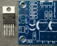
Thsi is what a fake LM1875T looks like
Curiosity got the better of me. I put the just-received obviously-fake LM1875 into my working board and tested it. I have no idea what this thing is, but I doubt it is even a 2030. Distortion was so high that I had to lower the drive level a bit to stop it from overloading the analyzer input. (No, it wasn't oscillating). But even then, absolute cr@p! 2nd harmonic only 20dB down from the fundamental!
Many folks have said "It makes no financial sense to fake such a cheap chip". Well, apparently it does to someone... This thing makes the authentic chip, which I don't particularly like, look pretty good")
Curiosity got the better of me. I put the just-received obviously-fake LM1875 into my working board and tested it. I have no idea what this thing is, but I doubt it is even a 2030. Distortion was so high that I had to lower the drive level a bit to stop it from overloading the analyzer input. (No, it wasn't oscillating). But even then, absolute cr@p! 2nd harmonic only 20dB down from the fundamental!
Many folks have said "It makes no financial sense to fake such a cheap chip". Well, apparently it does to someone... This thing makes the authentic chip, which I don't particularly like, look pretty good
Attachments
- Status
- This old topic is closed. If you want to reopen this topic, contact a moderator using the "Report Post" button.
- Home
- Amplifiers
- Chip Amps
- Complete chip amp kit with enclosure, etc ?